1.
INSTALL FRONT POWER WINDOW REGULATOR MOTOR ASSEMBLY (for Front Door)
NOTICE:
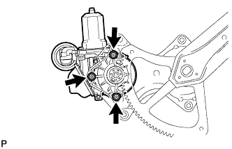
The regulator arm must be below the intermediate position when installing the power window regulator motor.
Using a "TORX" driver (T25), install the front power window regulator motor sub-assembly with the 3 screws.
Torque:
5.4 N*m{
55 kgf*cm
, 48 in.*lbf
}
HINT:
A new front window regulator adopts a self-tapping method. The installation position of the regulator will be threaded when the self-tapping screw is inserted.
2.
INSTALL FRONT DOOR WINDOW REGULATOR SUB-ASSEMBLY (for Front Door)
Apply MP grease to the sliding parts of the front door window regulator sub-assembly.
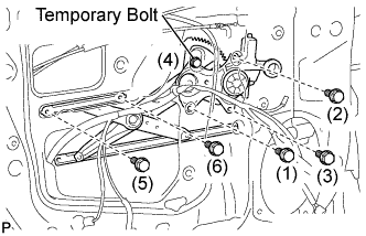
Install the temporary bolt to the front door window regulator sub-assembly.
Temporarily install the window regulator.
Tighten the 6 bolts in the order shown in the illustration to install the front window regulator.
Torque:
8.0 N*m{
82 kgf*cm
, 71 in.*lbf
}
3.
INSTALL FRONT DOOR GLASS SUB-ASSEMBLY (for Front Door)
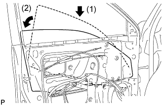
Insert the front door glass sub-assembly into the front door panel along the front door glass run as indicated in the order of the arrows in the illustration.
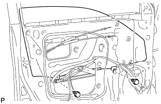
Install the front door glass sub-assembly with the 2 bolts.
Torque:
8.0 N*m{
82 kgf*cm
, 71 in.*lbf
}
Install the hole plug.
4.
INSTALL FRONT DOOR SERVICE HOLE COVER (for Front Door)
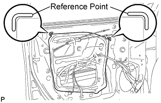
Apply butyl tape to the front door panel.
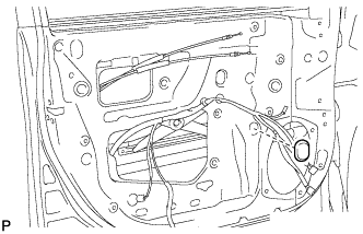
Pass the front door lock remote control cable and rear door inside the locking cable through a new front door service hole cover.
Attach the front door service hole cover according to the reference points on the front door panel.
NOTICE:
Securely install the front door service hole cover avoiding wrinkles and air bubbles.
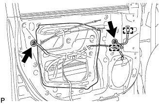
Connect each connector.
Engage the 2 clamps.
5.
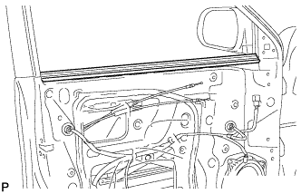
INSTALL FRONT DOOR INNER GLASS WEATHERSTRIP (for Front Door)
Install the front door inner glass weatherstrip.
6.
INSTALL FRONT DOOR TRIM BOARD SUB-ASSEMBLY (for Front Door)
Connect the connector.
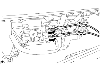
Connect the front door lock remote control cable and front door inside locking cable to the front door inside handle sub-assembly.
Engage the 2 clamps.
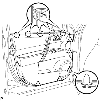
Engage the front door trim board with the 5 claws on the front door inner glass weatherstrip.
Engage the 9 clips.
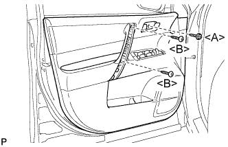
Install the 2 screws <B>.
Install the screw <A> and front door trim board to the front door panel.
Torque:
3.5 N*m{
36 kgf*cm
, 31 in.*lbf
}
7.
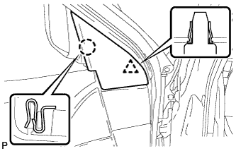
INSTALL COURTESY LIGHT ASSEMBLY (for Front Door)
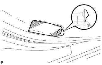
Connect the connector.
Engage the claw and install the courtesy light assembly.
8.
INSTALL ASSIST GRIP COVER (for Front Door)
Engage the 4 claws and install the assist grip cover.
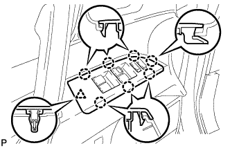
9.
INSTALL FRONT ARMREST UPPER BASE PANEL (for Front Door)
Connect the connector.
Engage the 7 claws and clip and install the front armrest upper base panel.
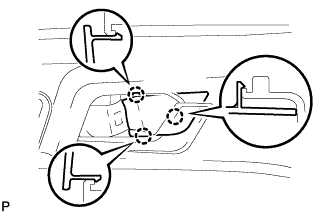
10.
INSTALL FRONT DOOR INSIDE HANDLE BEZEL PLUG (for Front Door)
Engage the 3 claws and install the front door inside handle bezel plug.
11.
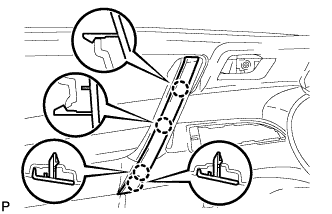
INSTALL FRONT DOOR LOWER FRAME BRACKET GARNISH (for Front Door)
Engage the clip and claw, and install the front door lower frame bracket garnish.
12.
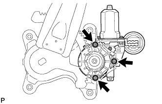
INSTALL REAR POWER WINDOW REGULATOR MOTOR ASSEMBLY (for Rear Door)
NOTICE:
The regulator arm must be below the intermediate position when installing the rear power window regulator motor assembly.
Using a "TORX" driver (T25), install the rear power window regulator motor assembly with the 3 screws.
Torque:
5.4 N*m{
55 kgf*cm
, 48 in.*lbf
}
HINT:
A new rear window regulator uses self-tapping screws to thread new installation holes when the self-tapping screws are inserted.
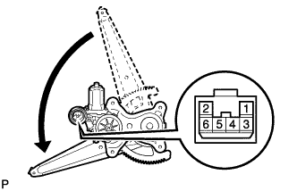
Connect the positive (+) lead of the battery to terminal 1, and the negative (-) lead to terminal 2 of the rear power window regulator motor assembly to move the lift arm to the position shown in the illustration.
13.
INSTALL REAR DOOR WINDOW REGULATOR SUB-ASSEMBLY (for Rear Door)
Apply MP grease to the sliding parts of the rear door window regulator sub-assembly.
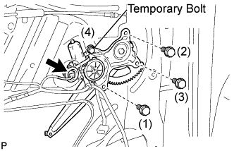
Install the temporary bolt to the rear door window regulator sub-assembly.
Temporarily install the window regulator.
Tighten the 4 bolts in the order shown in the illustration to install the rear door window regulator.
Torque:
8.0 N*m{
82 kgf*cm
, 71 in.*lbf
}
Connect the connector.
14.
INSTALL REAR DOOR GLASS SUB-ASSEMBLY (for Rear Door)
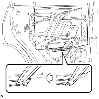
Slide the rear door glass sub-assembly to install it as shown in the illustration.
15.
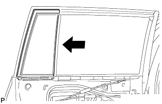
INSTALL REAR DOOR QUARTER WINDOW GLASS (for Rear Door)
Install the rear door quarter window glass to the rear door quarter window weatherstrip.
Install the rear door quarter window glass together with the rear door quarter window weatherstrip in the direction indicated by the arrow in the illustration.
16.
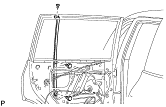
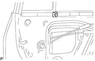
INSTALL REAR DOOR WINDOW DIVISION BAR SUB-ASSEMBLY (for Rear Door)
Insert the rear door window division bar sub-assembly from above.
Install the rear door glass run to the rear door lower window frame sub-assembly.
Install the rear door window division bar sub-assembly with the 2 bolts and screw.
Install the rear door vent seal.
17.
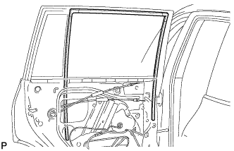
INSTALL REAR DOOR GLASS RUN (for Rear Door)
Install the rear door glass run.
18.
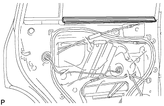
INSTALL REAR DOOR WEATHERSTRIP (for Rear Door)
Install the front door weatherstrip.
19.
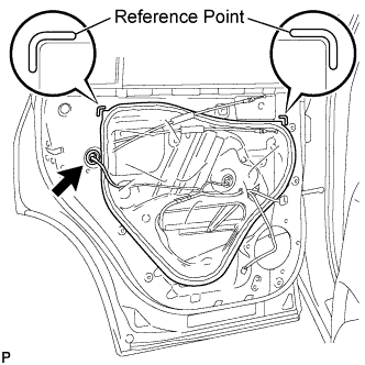
INSTALL REAR DOOR SERVICE HOLE COVER (for Rear Door)
Apply butyl tape to the rear door panel.
Pass the rear door lock remote control cable, rear door inside locking cable and each connector through a new rear door service hole cover.
Attach the rear door service hole cover according to the reference points on the rear door panel.
NOTICE:
Securely install the rear door service hole cover avoiding wrinkles and air bubbles.
Connect the connector.
20.
INSTALL REAR DOOR INNER GLASS WEATHERSTRIP (for Rear Door)
Install the rear door inner glass weatherstrip.
21.
INSTALL REAR DOOR TRIM BOARD SUB-ASSEMBLY (for Rear Door)
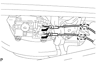
Connect the rear door lock remote control cable and rear door inside locking cable to the rear door inside handle sub-assembly.
Engage the 2 clamps.
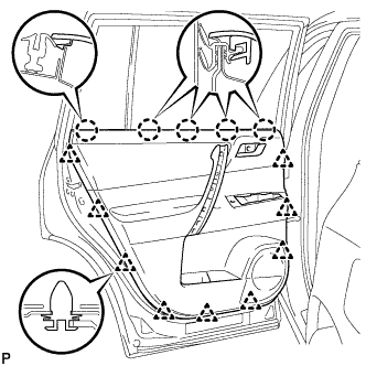
Engage the rear door trim board with the 5 claws on the rear door inner glass weatherstrip.
Engage the 9 clips and install the rear door trim board to the rear door panel.
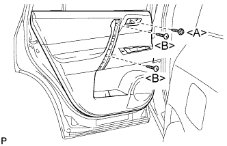
Install the 2 screws <B>.
Install the screw <A>.
Torque:
3.5 N*m{
36 kgf*cm
, 31 in.*lbf
}
22.
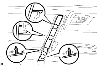
INSTALL DOOR ASSIST GRIP COVER (for Rear Door)
Engage the 4 claws and install the door assist grip cover.
23.
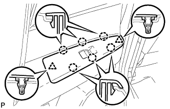
INSTALL REAR DOOR ARMREST UPPER BASE PANEL (for Rear Door)
Connect the connector.
Engage the 6 claws and 2 clips and install the rear door armrest upper base panel.