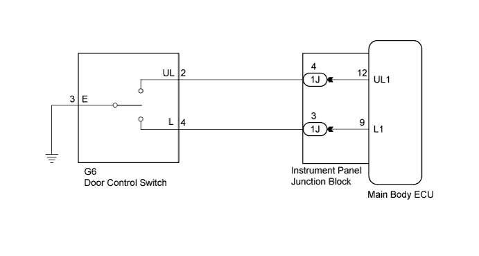
POWER DOOR LOCK CONTROL SYSTEM > All Doors LOCK/UNLOCK Functions do not Operate Via Door Control Switch |
| 1.INSPECT DOOR CONTROL SWITCH ASSEMBLY (DOOR LOCK AND UNLOCK SWITCH) |
Remove the door control switch (Click here).
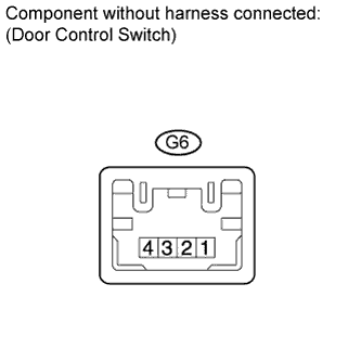 |
Measure the resistance according to the value(s) in the table below.
| Tester Connection | Switch Condition | Specified Condition |
| 4 - 3 | Locked | Below 1 Ω |
| 4 - 3 2 - 3 | OFF (Free) | 10 kΩ or higher |
| 2 - 3 | Unlocked | Below 1 Ω |
|
| ||||
| OK | |
 |
| 2.CHECK HARNESS AND CONNECTOR (DOOR CONTROL SWITCH CIRCUIT) |
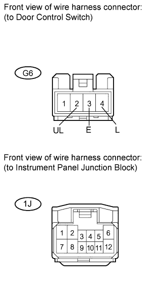 |
Disconnect the instrument panel junction block connector.
Measure the resistance according to the value(s) in the table below.
| Tester Connection | Condition | Specified Condition |
| G6-2 (UL) - 1J-4 | Always | Below 1 Ω |
| G6-4 (L) - 1J-3 | Always | Below 1 Ω |
| G6-3 (E) - Body ground | Always | Below 1 Ω |
| G6-2 (UL) - Body ground | Always | 10 kΩ or higher |
| G6-4 (L) - Body ground | Always | 10 kΩ or higher |
|
| ||||
| OK | ||
 | ||
| ||
