 |
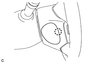
Disengage the claw and remove the lower No. 3 steering wheel cover.
STEERING COLUMN ASSEMBLY > REMOVAL |
| 1. PRECAUTION |
| 2. ALIGN FRONT WHEELS FACING STRAIGHT AHEAD |
| 3. DISCONNECT CABLE FROM NEGATIVE BATTERY TERMINAL |
| 4. REMOVE FRONT WHEEL LH |
| 5. REMOVE LOWER NO. 3 STEERING WHEEL COVER |
|
Disengage the claw and remove the lower No. 3 steering wheel cover.
| 6. REMOVE LOWER NO. 2 STEERING WHEEL COVER |
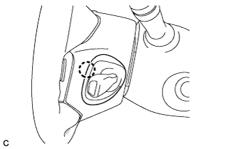 |
Disengage the claw and remove the lower No. 2 steering wheel cover.
| 7. REMOVE STEERING PAD |
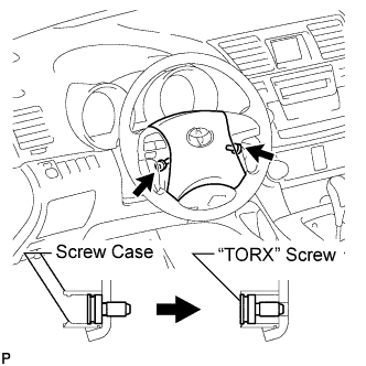 |
Using a "TORX" socket wrench (T30), loosen the 2 "TORX" screws until the groove along the screw circumference catches on the screw case.
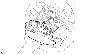 |
Pull out the steering pad from the steering wheel assembly and support the steering pad with one hand as shown in the illustration.
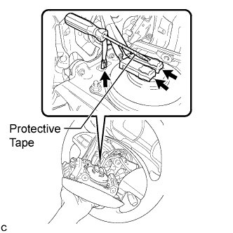 |
Disconnect the horn connector from the steering pad.
Using a screwdriver with the tip wrapped with protective tape, disconnect the 2 airbag connectors and remove the steering pad.
| 8. REMOVE STEERING WHEEL ASSEMBLY |
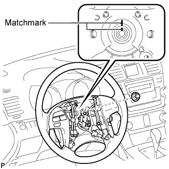 |
Remove the steering wheel assembly set nut.
Put matchmarks on the steering wheel assembly and the steering main shaft.
Disconnect the connectors from the spiral cable.
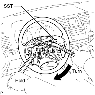 |
Using SST, remove the steering wheel assembly.
| 9. REMOVE FRONT DOOR SCUFF PLATE LH |
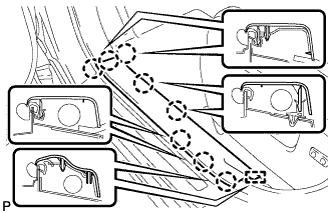 |
Disengage the 8 claws and guide, and remove the front door scuff plate LH.
| 10. REMOVE COWL SIDE TRIM SUB-ASSEMBLY LH |
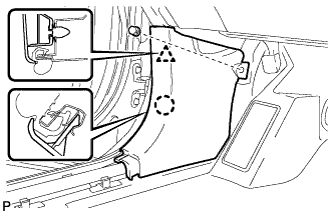 |
Remove the clip.
Disengage the clip and claw, and remove the cowl side trim sub-assembly LH.
| 11. REMOVE LOWER INSTRUMENT PANEL FINISH PANEL SUB-ASSEMBLY (for Manual Air Conditioning System) |
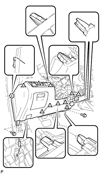 |
Remove the 2 bolts <B>.
Disengage the 3 claws and 10 clips.
Disconnect each connector.
Disconnect the hood lock control cable assembly and remove the lower instrument panel finish panel sub-assembly.
| 12. REMOVE LOWER INSTRUMENT PANEL FINISH PANEL SUB-ASSEMBLY (for Automatic Air Conditioning System) |
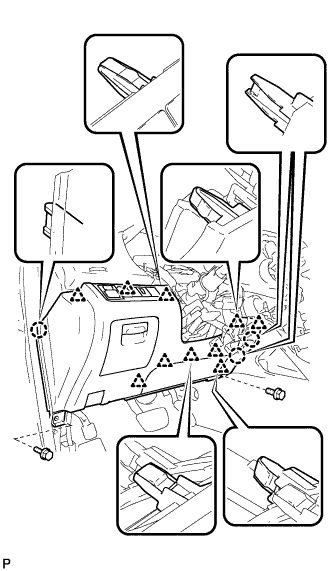 |
Remove the 2 bolts <B>.
Disengage the 3 claws and 10 clips.
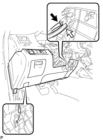 |
Disconnect each connector and the aspirator duct.
Disconnect the hood lock control cable assembly and remove the lower instrument panel finish panel sub-assembly.
| 13. REMOVE DRIVER SIDE KNEE AIRBAG ASSEMBLY |
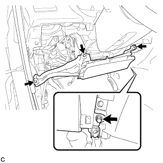 |
Remove the 4 bolts.
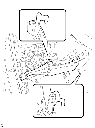 |
Disengage the 2 hooks.
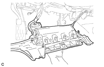 |
Pull out the driver side knee airbag assembly from the vehicle and support the driver side knee airbag assembly with one hand as shown in the illustration.
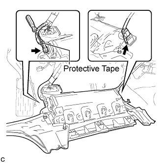 |
Disconnect the tire pressure warning reset switch connector.
Using a screwdriver with the tip wrapped with protective tape, disconnect the driver side knee airbag connector.
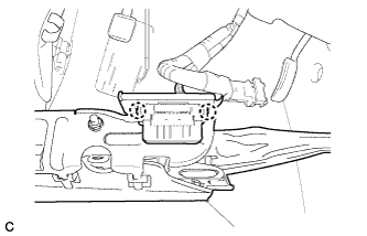 |
Disengage the 2 claws and separate the DLC3 from the driver side knee airbag assembly.
| 14. REMOVE BRAKE PEDAL RETURN SPRING |
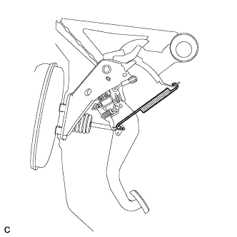 |
Remove the brake pedal return spring from the push rod pin and instrument panel reinforcement.
| 15. REMOVE STOP LIGHT SWITCH ASSEMBLY |
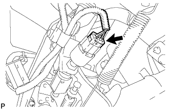 |
Disconnect the connector.
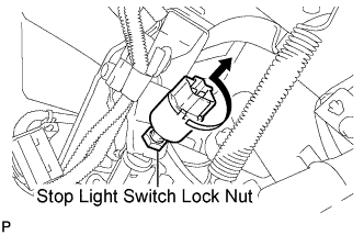 |
Loosen the stop light switch lock nut and remove the stop light switch assembly.
| 16. SEPARATE BRAKE MASTER CYLINDER PUSH ROD CLEVIS |
Remove the clip and push rod pin, and separate the brake master cylinder push rod clevis from the brake pedal sub-assembly.
| 17. REMOVE BRAKE PEDAL SUPPORT SUB-ASSEMBLY |
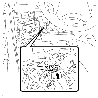 |
Disconnect the brake pedal load sensing switch connector and disengage the clamp.
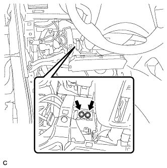 |
Remove the 2 bolts and separate the brake pedal support sub-assembly from the instrument panel reinforcement.
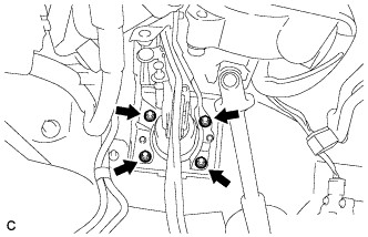 |
Remove the 4 nuts and brake pedal support sub-assembly from the body.
| 18. REMOVE STEERING COLUMN COVER |
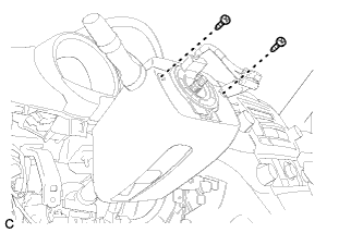 |
Remove the 2 screws.
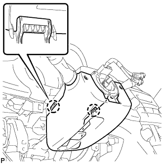 |
Disengage the 2 claws to remove the lower steering column cover.
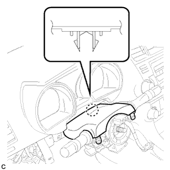 |
Disengage the claw to remove the upper steering column cover.
| 19. REMOVE TURN SIGNAL SWITCH ASSEMBLY WITH SPIRAL CABLE SUB-ASSEMBLY |
Disconnect the connectors from the turn signal switch assembly with spiral cable sub-assembly.
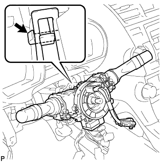 |
Using pliers, grip the claws of the clip and remove the turn signal switch assembly with spiral cable sub-assembly.
| 20. REMOVE NO. 1 AIR DUCT SUB-ASSEMBLY |
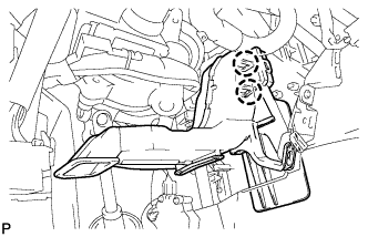 |
Disengage the 2 claws and remove the No. 1 air duct sub-assembly.
| 21. SEPARATE STEERING INTERMEDIATE SHAFT SUB-ASSEMBLY |
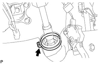 |
Loosen the bolt.
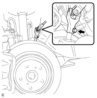 |
Remove the bolt and slide the steering intermediate shaft sub-assembly.
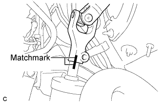 |
Put matchmarks on the steering intermediate shaft sub-assembly and the power steering link assembly.
Separate the steering intermediate shaft sub-assembly from the power steering link assembly.
| 22. REMOVE STEERING COLUMN ASSEMBLY |
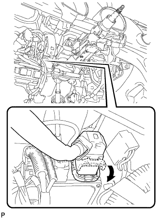 |
Disconnect the connector from the power steering ECU assembly.
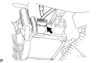 |
Disconnect the connector from the power steering ECU assembly.
Disconnect the connectors and disengage the wire harness clamps from the steering column assembly.
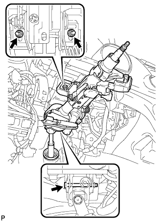 |
Remove the bolt, 2 nuts, and the steering column assembly.
| 23. REMOVE STEERING INTERMEDIATE SHAFT SUB-ASSEMBLY |
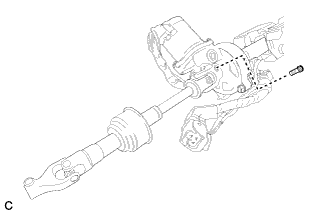 |
Remove the bolt.
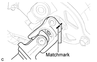 |
Put matchmarks on the steering intermediate shaft sub-assembly and the steering column assembly.
Remove the steering intermediate shaft sub-assembly from the steering column assembly.