Home › INTRODUCTION › INTRODUCTION › REPAIR INSTRUCTION

REPAIR INSTRUCTION > INITIALIZATION


PROCEDURES NECESSARY WHEN BATTERY TERMINAL IS DISCONNECTED/RECONNECTED

Necessary Procedures
Procedure Details
Effects / Inoperative Functions When Necessary Procedures are not Performed
Notes
Reset back door close position
Fully close the back door to turn off the courtesy switch.
Power back door function
If the back door is closed when disconnecting the cable from the battery terminal, it is not necessary to reset it.

NOTICE:
It may not be possible to release the steering lock or start the engine when the battery voltage is low. If this occurs, initialization of the steering lock system is required. (Click here)


PROCEDURES NECESSARY WHEN ECU OR OTHER PARTS ARE REPLACED

Replacement Part
Necessary Procedures
Effects / Inoperative Functions when Necessary Procedures are not Performed
Notes
  1. Automatic transaxle assembly
  2. Engine assembly
Reset memory
  1. Large shift shock
  2. The deterioration of fuel efficiency
Using Techstream.
ECM
Reset memory
  1. Large shift shock
  2. The deterioration of fuel efficiency
Using Techstream.
ECU communication ID registration
Engine start
-
Vehicle Identification Number (VIN) registration
MIL comes on
Using Techstream.
Tire pressure warning ECU
  1. Register transmitter IDs
  2. Initialize tire pressure warning system
  1. When DTC detection conditions of "transmitter ID not received" DTC are met, TPWS indicator blinks for 1 minute, and then illuminates.
  2. Tire pressure monitoring function
-
Tire pressure warning valve and transmitter
  1. Register transmitter IDs
  2. Initialize tire pressure warning system
  1. When DTC detection conditions of "transmitter ID not received" DTC are met, TPWS indicator blinks for 1 minute, and then illuminates.
  2. Tire pressure monitoring function of replaced wheel
Even if only one wheel is replaced, IDs for all 4 or 5 wheels must be registered.
  1. Yaw rate and acceleration sensor
  2. Brake actuator
  1. Clear zero point calibration data
  2. Perform yaw rate and acceleration sensor zero point calibration
  1. Slip indicator light comes on
  2. VSC disabled or malfunctioning
Perform yaw rate and acceleration sensor zero point calibration with the ignition switch on (engine stopped).
Steering lock actuator (Steering lock ECU) (*1)
ECU code registration
Engine start
-
  1. Occupant Classification ECU
  2. Front seat assembly
  1. Perform zero point calibration
  2. Sensitivity check
  1. Occupant classification system
  2. Passenger airbag ON/OFF indicator
  3. Airbag system (Front passenger side)
  4. Seat belt warning system (Front passenger side)
-
  1. Certification ECU (*1)
  2. Electrical key transmitter (*1)
Key ID registration
  1. Wireless door lock control system
  2. Smart key System
  3. Engine start
-
ID code box (*1)
  1. ECU code registration
  2. ECU communication ID registration
  1. Wireless door lock control system
  2. Smart key System
  3. Engine start
-
Transponder key ECU (*2)
  1. Key code registration
  2. ECU communication ID registration
Engine start
-
Door control transmitter (*2)
Key code registration
Engine start
-
Refer to wireless door lock control system (w/o Smart key System) "REGISTRATION" procedures
Wireless door lock control system
-
Door control receiver (*2)
Refer to wireless door lock control system (w/o Smart key System) "REGISTRATION" procedures
Wireless door lock control system
-
  1. Power window regulator motor (Driver door)
  2. Front door window regulator (Driver door)
Perform power window reset (initialization of pulse sensor)
  1. Automatic door glass open/close function
  2. Jam protection function
  3. Operation function after ignition switch off
  4. Operation of each passenger window using power window switch at the driver door
Necessary when removed and installed.
Back door lock motor
Reset back door close position
Power back door function
-
  1. Sliding roof drive gear sub-assembly (Sliding roof ECU)
  2. Sliding roof housing
  3. Sliding roof drive cable
Perform sliding roof drive gear reset
  1. Automatic open/close function of roof glass
  2. Jam protection function
  3. Operation function after ignition switch off
Necessary when removed and installed (Not necessary when the sliding roof drive gear (sliding roof ECU) is removed and installed together with the sliding roof housing).

HINT:
  1. *1: w/ Smart key System
  2. *2: w/o Smart key System


RESET MEMORY (Automatic Transaxle System)

NOTICE:
  1. Perform the RESET MEMORY (AT initialization) when replacing the automatic transaxle assembly, engine assembly or ECM.
  2. The RESET MEMORY can be performed only with Techstream.

HINT:
The ECM memorizes the condition that the ECT controls the automatic transaxle assembly and engine assembly according to those characteristics. Therefore, when the automatic transaxle assembly, engine assembly, or ECM has been replaced, it is necessary to reset the memory so that the ECM can memorize the new information.
Reset procedure is as follows.

  1. Turn the ignition switch off.

  2. Connect Techstream to the DLC3.

  3. Turn the ignition switch on (IG) and push the Techstream main switch on.

  4. Enter the following menu: Powertrain / Engine and ECT / Utility / Reset Memory. Then, press "Next".

  5. Perform the reset memory procedure from the main menu.

    CAUTION:
    After performing the RESET MEMORY, be sure to perform the ROAD TEST (Click here) described earlier.

    HINT:
    The ECM is learned by performing the ROAD TEST.


DESCRIPTION OF CODE REGISTRATION (Engine Immobiliser System (w/ Smart Key System))

HINT:
  1. The ID codes are the same as recognition codes for the wireless transmitter and the engine immobiliser function. Registering an ID code enables the smart key system, the wireless door lock control function and the engine immobiliser function to be operated.
  2. Code registration is necessary when the certification ECU (smart key ECU assembly), ID code box (immobiliser code ECU), steering lock ECU, or key is replaced with a new one.


  1. Vehicles with the smart key system do not have a key slot. Therefore, hold the key close to the engine switch to register the key, as shown in the illustration below.
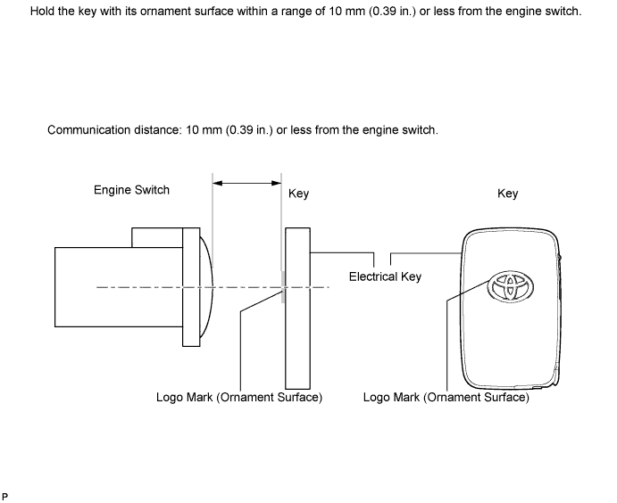

    B139204E05


PART REPLACEMENT AND KEY REGISTRATION (Engine Immobiliser System (w/ Smart Key System))
  1. The following table shows ECU replacement and key registration procedures for cases in which a malfunctioning ECU has been identified through the troubleshooting of the smart key system.

    HINT:
    1. The following procedures can be performed:
      1. New key ID registration
      2. Additional key ID registration
      3. Key ID erasure
      4. All key ID erasure
      5. ECU code registration
    2. If the customer has not brought all the registered keys, replacement of the ID code box (immobiliser code ECU) is also required.
    3. A maximum of 7 keys can be registered.


    Part to be replaced
    Condition
    Procedure
    Reference
    Certification ECU (Smart key ECU assembly)
    Customer has brought all keys
    1. Replace certification ECU (smart key ECU assembly)
    -
    2. Reregister all keys (New key ID registration)
    PROCEDURE "B"
    Some keys are lost
    Key ID codes can be registered and erased
    1. Erase key codes (Key ID erasure)
    PROCEDURE "D"
    2. Perform additional key registration procedure (Additional key ID registration)
    PROCEDURE "C"
    3. Replace certification ECU (smart key ECU assembly)
    -
    4. Reregister all keys (New key ID registration)

    HINT:
    If some keys are not registered during the above steps, they will be disabled because they cannot be registered later.

    PROCEDURE "B"
    Key ID codes cannot be either registered or erased
    1. Replace certification ECU (smart key ECU assembly)
    -
    2. Replace ID code box (immobiliser code ECU)
    -
    3. Reregister all keys (New key ID registration)

    HINT:
    If key codes cannot be erased or additional keys cannot be registered due to a malfunction in the certification ECU (smart key ECU assembly), replace the ID code box (immobiliser code ECU) and certification ECU (smart key ECU assembly). If some keys are not registered during the above steps, they will be disabled because they cannot be registered later.

    PROCEDURE "A"
    4. ECU communication ID registration
    PROCEDURE "G"
    Certification ECU (Smart key ECU assembly)
    All keys are lost
    1. Replace certification ECU (smart key ECU assembly)
    -
    2. Replace ID code box (immobiliser code ECU)
    -
    3. Reregister all keys (New key ID registration)

    HINT:
    If key codes cannot be erased or additional keys cannot be registered due to a malfunction in the certification ECU (smart key ECU assembly), replace the ID code box (immobiliser code ECU) and certification ECU (smart key ECU assembly). If some keys are not registered during the above steps, they will be disabled because they cannot be registered later.

    PROCEDURE "A"
    4. ECU communication ID registration
    PROCEDURE "G"
    ID code box (Immobiliser code ECU)
    Customer has brought at least 1 key
    1. Replace ID code box (immobiliser code ECU)
    -
    2. Register recognition codes in ECUs (ECU code registration)
    PROCEDURE "F"
    3. ECU communication ID registration
    PROCEDURE "G"
    All keys are lost
    1. Replace ID code box (immobiliser code ECU)
    -
    2. Replace certification ECU (smart key ECU assembly)
    -
    3. Reregister all keys (New key ID registration)

    HINT:
    If some keys are not registered during the above steps, they will be disabled because they cannot be registered later.

    PROCEDURE "A"
    4. ECU communication ID registration
    PROCEDURE "G"
    Steering lock ECU
    Customer has brought at least 1 key
    1. Replace steering lock ECU
    -
    2. Register recognition codes in ECUs (ECU code registration)
    PROCEDURE "F"
    All keys are lost
    1. Replace steering lock ECU
    -
    2. Replace certification ECU (smart key ECU assembly)
    -
    3. Replace ID code box (immobiliser code ECU)
    -
    4. Reregister all keys (New key ID registration)

    HINT:
    If some keys are not registered during the above steps, they will be disabled because they cannot be registered later.

    PROCEDURE "A"
    5. ECU communication ID registration
    PROCEDURE "G"
    Main body ECU (Instrument panel junction block)
    No condition required
    Replace main body ECU (instrument panel junction block)
    -
    ECM
    No condition required
    1. Replace ECM
    -
    2. ECU communication ID registration
    PROCEDURE "H"
    Key (for replacement)
    Customer has brought at least 1 key
    1. Using remaining key, erase lost key code (Key ID erasure)
    PROCEDURE "D"
    2. Register additional keys as necessary (Additional key ID registration)
    PROCEDURE "C"
    All keys are lost
    1. Erase all key codes (All key ID erasure)
    PROCEDURE "E"
    2. Register all keys (New key ID registration)

    HINT:
    If the customer brings lost keys at a later date, they can be registered using the additional key ID registration function.

    PROCEDURE "A"
    Key (for addition)
    Customer has brought at least 1 key

    HINT:
    When adding keys (Additional registration)

    1. Register additional keys as necessary (Additional key ID registration)
    PROCEDURE "C"


KEY REGISTRATION (Engine Immobiliser System (w/ Smart Key System))
  1. PROCEDURE "A"
    New key ID registration (when replacing the certification ECU (smart key ECU assembly) and ID code box (immobiliser code ECU), or when replacing the certification ECU (smart key ECU assembly), ID code box (immobiliser code ECU) and steering lock ECU)

    Process
    Procedure
    1. Start of registration
    1. Connect Techstream to DLC3
    2. Turn engine switch on (IG)
    3. Select "Body Electrical / Smart Key / Utility / Smart Code Registration" from the Techstream menu

    HINT:
    The engine switch cannot be turned on (IG) more than 10 times. After connecting Techstream, turn Techstream on while turning the driver's side door courtesy light switch on and off repeatedly at 1.5-second intervals or less to continue key registration procedure.

    2. Confirmation of ECU code
    1. Perform operation according to prompts on the Techstream screen

    HINT:
    Mode is automatically selected by Techstream (new registration mode or add mode).

    3. Verification of unregistered key *1
    1. Hold unregistered key close to engine switch (For details, refer to "DESCRIPTION OF CODE REGISTRATION")
    2. Confirm that wireless door lock buzzer sounds once (short beep)
    3. Place unregistered key on driver's seat
    4. Confirm that wireless door lock buzzer sounds once (short beep)
    4. Registration of ID code
    1. Perform operation according to prompts on the Techstream screen
    5. End of registration
    1. Finish new key ID code registration

    1. *1: Repeat this process for each key which is to be registered for the vehicle. Finish the procedure for each key within 30 seconds. If the procedure for any of the keys has not been finished within the specified time, perform the registration procedures again from process 1. Make sure that only 1 key is in the cabin during the registration procedures. If 2 or more keys are in the cabin simultaneously, electric waves will interfere with each other, preventing normal registration.

  2. PROCEDURE "B"
    New key ID registration (when replacing the certification ECU (smart key ECU assembly))

    Process
    Procedure
    1. Start of registration
    1. Connect Techstream to DLC3
    2. Turn engine switch on (IG)
    3. Select "Body Electrical / Smart Key / Utility / Smart Code Registration" from the Techstream menu

    HINT:
    The engine switch cannot be turned on (IG) more than 10 times. After connecting Techstream, turn Techstream on while turning the driver's side door courtesy light switch on and off repeatedly at 1.5-second intervals or less to continue key registration procedure.

    2. Confirmation of ECU code
    1. Perform operation according to prompts on the Techstream screen

    HINT:
    Mode is automatically selected by Techstream (new registration mode or add mode).

    3. Confirmation of all registered keys *1
    1. Hold unregistered key close to engine switch (For details, refer to "DESCRIPTION OF CODE REGISTRATION")
    2. Confirm that wireless door lock buzzer sounds once (short beep)
    4. Confirmation of ECU code
    1. Perform operation according to prompts on the Techstream screen
    5. Verification of unregistered key *2
    1. Hold unregistered key close to engine switch (For details, refer to "DESCRIPTION OF CODE REGISTRATION")
    2. Confirm that wireless door lock buzzer sounds once (short beep)
    3. Place unregistered key on driver's seat
    4. Confirm that wireless door lock buzzer sounds once (short beep)
    5. Registration of ID code
    1. Perform operation according to prompts on the Techstream screen
    6. End of registration
    1. Finish new key ID code registration

    1. *1: Repeat this process for each key registered for the vehicle. Finish the procedure for each key within 30 seconds. If the procedure for any of the keys has not been finished within the specified time, perform the registration procedures again from process 1. If the key confirmation procedure for a key is performed, the security indicator light comes on and remains on until all the keys are confirmed.
    2. *2: Repeat this process for each key which is to be registered for the vehicle. Finish the procedure for each key within 30 seconds. If the procedure for any of the keys is not finished within the specified time, perform the registration procedures again from 1. Make sure that only 1 key is in the cabin during the registration procedures. If 2 or more keys are in the cabin simultaneously, electric waves will interfere with each other, preventing normal registration.

  3. PROCEDURE "C"
    Additional key ID registration

    Process
    Procedure
    1. Start of registration
    1. Connect Techstream to DLC3
    2. Turn engine switch on (IG)
    3. Select "Body Electrical / Smart Key / Utility / Smart Code Registration" from the Techstream menu
    2. Confirmation of registered key *1
    1. Perform operation according to prompts on the Techstream screen

      HINT:
      Mode is automatically selected by Techstream (new registration mode or add mode)

    2. Hold unregistered key close to engine switch (For details, refer to "DESCRIPTION OF CODE REGISTRATION")
    3. Confirm that wireless door lock buzzer sounds once (short beep)
    3. Confirmation of ECU code
    1. Perform operation according to prompts on the Techstream screen
    4. Verification of unregistered key *2
    1. Hold unregistered key close to engine switch (For details, refer to "DESCRIPTION OF CODE REGISTRATION")
    2. Confirm that wireless door lock buzzer sounds once (short beep)
    3. Place unregistered key on driver's seat
    4. Confirm that wireless door lock buzzer sounds once (short beep)
    5. Registration of ID code
    1. Perform operation according to prompts on the Techstream screen
    6. End of registration
    1. Finish additional key ID code registration

    1. *1: Perform this process for one of the keys registered for the vehicle. Finish the procedure within 30 seconds. If the procedure has not been finished within the specified time, perform the registration procedures again from process 1.
    2. *2: Repeat this process for each key which is to be registered for the vehicle. Finish the procedure for each key within 30 seconds. If the procedure for any of the keys is not finished within the specified time, perform the registration procedures again from 1. Make sure that only 1 key is in the cabin during the registration procedures. If 2 or more keys are in the cabin simultaneously, electric waves will interfere with each other, preventing normal registration.

  4. PROCEDURE "D"
    Key ID erasure

    HINT:
    Erase all registered key codes except one.


    Process
    Procedure
    1. Start of erasure
    1. Connect Techstream to DLC3
    2. Turn engine switch on (IG)
    3. Select "Body Electrical / Smart Key / Utility / Smart Code Erasure" from the Techstream menu
    2. Confirmation of registered key *1

    HINT:
    Select the key that will not be erased.

    1. Perform operation according to prompts on the Techstream screen
    2. Hold registered key close to engine switch (For details, refer to "DESCRIPTION OF CODE REGISTRATION")
    3. Confirm that wireless door lock buzzer sounds once (short beep)
    3. Confirmation of ECU code
    1. Perform operation according to prompts on the Techstream screen
    4. Erasure of ID code
    1. Perform operation according to prompts on the Techstream screen
    5. End of erasure
    1. Finish key ID code erasure
    1. *1: Perform this process for one of the keys registered for the vehicle. Finish the procedure within 30 seconds. If the procedure has not been finished within the specified time, perform the erasure procedures again from process 1.

  5. PROCEDURE "E"
    All key ID erasure

    HINT:
    All the key codes registered in the vehicle are erased.


    Process
    Procedure
    1. Start of erasure
    1. Connect Techstream to DLC3
    2. Turn engine switch on (IG)
    3. Turn Techstream on while turning driver side door courtesy light switch on and off repeatedly at 1.5-second intervals or less
    4. Select "Body Electrical / Smart Key / Utility / Smart Code Erasure" from the Techstream menu
    3. Confirmation of ECU code
    1. Perform operation according to prompts on the Techstream screen
    4. Erasure of ID code
    1. Perform operation according to prompts on the Techstream screen
    5. End of erasure
    1. Finish key ID code erasure

  6. PROCEDURE "F"
    ECU code registration

    Process
    Procedure
    1. Start of registration
    1. Connect Techstream to DLC3
    2. Turn engine switch on (IG)
    3. Select "Body Electrical / Smart Key / Utility / ECU Communication ID Registration" from the Techstream menu
    2. Confirmation of registered key *1
    1. Hold registered key close to engine switch (For details, refer to "DESCRIPTION OF CODE REGISTRATION")
    2. Confirm that wireless door lock buzzer sounds once (short beep)
    3. Registration of ECU code
    1. Perform operation according to prompts on the Techstream screen
    4. End of registration
    1. Finish ECU code registration

    1. *1: Perform this process for one of the keys registered for the vehicle. Finish the procedure within 30 seconds. If the procedure has not been finished within the specified time, perform the erasure procedures again from process 1.


  7. PROCEDURE "G"
    ECU communication ID registration

    NOTICE:
    1. The ECU communication ID should be registered when the ID code box (immobiliser code ECU) is replaced in order to match these ECU communication IDs.
    2. The engine cannot be started unless the ECU communication IDs match.
    3. After the registration, pressing the engine switch may not start the engine on the first try. If so, press the engine switch again.
    4. Erase DTC B2799 (code for ECM's immobiliser communication error) by either of the following:
      - Use Techstream.
      - Disconnect the battery for 30 seconds.


    1. Using SST, connect terminals TC and CG of the DLC3.
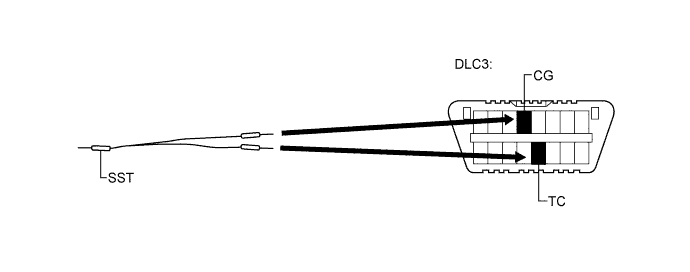
      SST
      09843-18040  

      B171404E01

    2. Turn the engine switch on (IG) and leave it as is for 30 minutes.

      HINT:
      Do not start the engine.

    3. Turn the engine switch off and disconnect terminals TC and CG.

    4. Check that the engine starts and stays on for more than 3 seconds.

  8. PROCEDURE "H"
    ECU communication ID registration

    NOTICE:
    The ECU communication ID should be registered when the ECM is replaced in order to match the ECU communication IDs.


    Procedure
    Security Indicator Light Condition
    1. Start
    OFF
    2. Hold an already registered key close to the engine switch and turn the engine switch on (IG) with the brake pedal depressed
    3. Check that the engine starts and stays on for more than 3 seconds
    4. Next
    5. End


DESCRIPTION OF CODE REGISTRATION (Engine Immobiliser System (w/o Smart Key System))

HINT:
The key has 2 codes: the key code (immobiliser code) and the wireless code. Both of these codes need to be registered. Refer to the page for the wireless code registration procedures.

  1. When adding master keys or sub keys (Additional registration):

    1. Register the key code (immobiliser code) in the transponder key ECU.

      Target ECU
      Refer to
      Transponder key ECU
      Procedure "B"

  2. When replacing the transponder key ECU (New registration):

    1. Register the key code (immobiliser code) in the transponder key ECU.

      Target ECU
      Refer to
      Transponder key ECU
      Procedure "A"

    2. Register the ECU communication ID between the new transponder key ECU and the ECM.

      Target ECU
      Refer to
      ECM
      Procedure "D"

  3. When replacing the ECM:

    1. Reregister the ECU communication ID between the transponder key ECU and the new ECM.

      Target ECU
      Refer to
      Transponder key ECU
      Procedure "E"

  4. When replacing the transponder key ECU and the ECM:

    1. Register the key codes (immobiliser codes) in the new transponder key ECU.

      Target ECU
      Refer to
      Transponder key ECU
      Procedure "A"

    2. Reregister the ECU communication ID between the new transponder key ECU and the new ECM.

      Target ECU
      Refer to
      Transponder key ECU
      Procedure "E"

  5. When erasing the key code(s):

    1. Erase the key code(s) of lost key(s).

      Target ECU
      Refer to
      Transponder key ECU
      Procedure "C"


KEY REGISTRATION (Engine Immobiliser System (w/o Smart Key System))


  1. New key code registration (Procedure "A"):

    NOTICE:
    No key codes are registered in the transponder key ECU.

    HINT:
    1. In this mode, a maximum of 3 key codes for 2 master keys and 1 sub-key can be registered. The master keys and sub-key can be registered in any order because the transponder key ECU can distinguish between different types of keys.
    2. New key codes must be registered with the battery connected. The ignition switch can be either on or off.
    3. When a new transponder key ECU is installed, key codes must be registered in the transponder key ECU.


    Automatic Key Code Registration (New Registration): 
    Procedure
    Security Indicator Light Condition
    1. Start
    Blinking

    HINT:
    Until first key is inserted

    2. Insert the master key into the ignition key cylinder.
    ON
    3. Techstream operation
    1. Select Body Electrical
    2. Select Immobiliser
    3. Select Utility
    4. Select Key Registration

      HINT:
      After completing the above operation, proceed to the next step in accordance with the prompts on the Techstream screen.

    OFF for 1 second and then ON
    4. Remove the key and then push the Next button on the tester.
    ON
    5. Insert the master key to be registered and then push the Next button on the tester.
    OFF for 1 second and then ON
    6. Remove the key and then push the Next button on the tester.
    ON
    5. Insert the sub-key to be registered and then push the Next button on the tester.
    OFF for 1 second and then ON for 0.5 seconds and then OFF
    8. Remove the key.
    Blinking
    7. End (Procedure "E")

    HINT:
    1. When the engine immobiliser system is operating normally and the key is pulled out, the security indicator light blinks continuously.
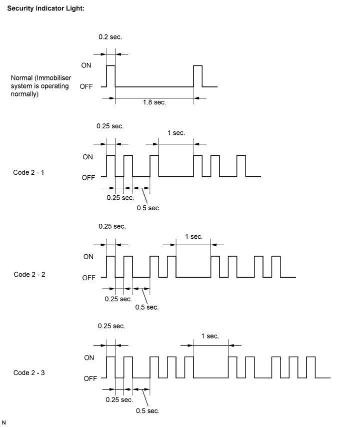
    2. If the new key code registration fails, code 2-1 will be output through the security indicator light. Trying to re-register an already registered key will cause code 2-2 to be output when the key is inserted. If the number of registered key codes exceeds the maximum limit, code 2-3 will be output through the security indicator light. The output details are shown below.


    B111593E19

  2. Finish the automatic key code registration mode. The automatic key code registration mode can be forced to end when at least 1 key code (immobiliser code) for the master key has been registered.

    HINT:
    1. w/o Techstream:
      Turn the ignition switch on and off 5 times within 10 seconds using the master key that has already been registered.
    2. w/ Techstream:
      Follow the instruction on the Techstream screen to end new key code registration mode.


REGISTRATION OF ADDITIONAL KEY (Engine Immobiliser System (w/o Smart Key System))
  1. Additional registration (Procedure "B"):

    HINT:
    1. A maximum of 5 key codes and 3 sub-key codes can be registered.
    2. Registration mode will end if any step is not completed within the specified time.
    3. When the ignition cylinder or the key cylinder set is replaced, remove the transmitter module from the original master key. Then install this transmitter module to a new key and use the new key as the master key. If necessary, use this master key to register other keys.

    NOTICE:
    When the ignition key cylinder has been replaced, locking and unlocking doors is possible with the new master key's transmitter module (removed from the original master key). However, the new master key will not be able to lock and unlock doors through the door key cylinder. Keep the original master key. If the battery in the new master key's transmitter module fails, the original master key can be used to lock and unlock doors through the door key cylinder.


    Additional Registration: 
    Procedure
    Time to Complete Operation
    Security Indicator Light Condition
    1. Start
    -
    Blinking

    HINT:
    Until first key is inserted

    2. Insert the already registered master key into the ignition key cylinder and turn the ignition switch on.
    -
    OFF
    3. Techstream operation
    1. Select Body Electrical
    2. Select Immobiliser
    3. Select Utility
    4. Select Key Registration

      HINT:
      After completing the above operation, proceed to the next step in accordance with the prompts on the Techstream screen.

    Within 120 sec.
    ON
    4. Remove the master key.
    Within 20 sec.

    HINT:
    After tester instruction

    ON
    5. Insert the key to be registered in the ignition key cylinder.
    Within 10 sec.
    Blinking
    6. Wait for 60 sec. after the key is registered.

    HINT:
    The security indicator light goes off.

    -
    OFF
    7. Remove the key.
    -
    Blinking
    8. End

    HINT:
    1. A brief outline of key code registration procedures is shown above. For detailed information, refer to the Techstream screen.
    2. When the engine immobiliser system is operating normally and the key is pulled out, the security indicator light blinks continuously.
    3. If the key code registration has failed in automatic key code registration mode, code 2-1 will be output through the security indicator light. Trying to re-register an already registered key will cause code 2-2 to be output when the key is inserted. If the number of registered key codes exceeds the maximum limit, code 2-3 will be output through the security indicator light. The details are shown in procedure "A".


ERASURE OF KEY CODE (Engine Immobiliser System (w/o Smart Key System))
  1. Erase key codes (Procedure "C").

    HINT:
    1. Performing this procedure will erase all key codes except for the master key, which is used for erasing the key codes. In order to use a key whose code has been erased, a new key code must be registered.
    2. This procedure will be canceled if each step is not completed within the specified time.


    Erasing Key Code: 
    Procedure
    Time to Complete Operation
    Security Indicator Light Condition
    1. Start
    -
    Blinking

    HINT:
    Until first key is inserted

    2. Insert the already registered master key in the ignition key cylinder and turn the ignition switch on.
    -
    OFF
    3. Techstream operation
    1. Select Body Electrical
    2. Select Immobiliser
    3. Select Utility
    4. Select Transponder Code Erasure

      HINT:
      After completing the above operation, proceed to the next step in accordance with the prompts on the Techstream screen.

    Within 120 sec.
    ON for 1 sec. then OFF
    4. Remove the master key.
    Within 10 sec.

    HINT:
    After tester instruction

    ON
    5. End

    HINT:
    1. A brief outline of key code registration procedures is shown above. For detailed information, refer to the Techstream screen.
    2. When the engine immobiliser system is operating normally and the key is pulled out, the security indicator light blinks continuously.


ECU COMMUNICATION ID REGISTRATION (Engine Immobiliser System (w/o Smart Key System))


  1. ECU communication ID registration (Procedure "D"):

    NOTICE:
    1. When the transponder key ECU is replaced, the ECU communication ID of the ECM must be registered into the transponder key ECU to match their ECU communication IDs.
    2. The engine cannot be started unless the ECU communication IDs match.
    3. Do not turn the ignition switch from on to off 20 times or more before setting the ECU communication ID. If this operation is likely to be performed 20 times or more, disconnect the cable from the negative battery terminal in order to avoid disabling engine start. Failure to do so will result in the engine not starting unless the transponder key ECU is replaced with a new one.
    4. After the registration, turning the ignition switch to the START position may not start the engine on the first try. If so, turn the ignition switch to the START position again.
    5. After the engine is started, erase DTC B2799 (code for ECM's immobiliser communication error) by either of the following:
      - Using Techstream.
      - Disconnecting the battery for 30 seconds.


    1. Using SST, connect terminals TC and CG of the DLC3.

      SST
      09843-18040  

      B171404E01

    2. Turn the ignition switch to the ON position and leave the vehicle as is for 30 minutes.

      HINT:
      Do not start the engine.

    3. Check that the engine starts.

  2. ECU communication ID registration (Procedure "E"):

    NOTICE:
    The ECU communication ID should be registered when the ECM and transponder key ECU are replaced or when the ECM only is replaced in order to match the ECU communication ID.


    Procedure
    Security Indicator Light Condition
    1. Start
    OFF
    2. Insert an already registered key into the ignition key cylinder.
    3. Engine start
    4. Check that the engine starts and stays on for more than 3 seconds.
    5. Next
    6. End


VEHICLE IDENTIFICATION NUMBER (VIN) REGISTRATION

NOTICE:
The Vehicle Identification Number (VIN) must be input into the replacement ECM.

HINT:
The VIN is a 17-digit alphanumeric vehicle identification number. The techstream is required to register the VIN.

  1. Description

    HINT:
    This registration section consists of two parts: Read VIN and Write VIN.


    1. Read VIN: Explains the VIN reading process in a flowchart. This process allows the VIN stored in the ECM to be read in order to confirm that the two VINs, provided with the vehicle and stored in the vehicle's ECM, are the same.

    2. Write VIN: Explains the VIN writing process in a flowchart. This process allows the VIN to be input into the ECM. If the ECM is changed, or the ECM VIN and vehicle VIN do not match, the VIN can be registered, or overwritten in the ECM by following this procedure.

  2. Read VIN

    1. Confirm the vehicle VIN.

    2. Connect the techstream to the DLC3.

    3. Turn the ignition switch on (IG).

    4. Turn the tester on.

    5. Select the following menu items: Powertrain / Engine and ECT / Utility / VIN / VIN Read.

  3. Write VIN

    1. Confirm the vehicle VIN.

    2. Connect the techstream to the DLC3.

    3. Turn the ignition switch on (IG).

    4. Turn the tester on.

    5. Select the following menu items: Powertrain / Engine and ECT / Utility / VIN / VIN Write.


DESCRIPTION OF CODE REGISTRATION (Tire Pressure Warning System)
It is necessary to register the transmitter IDs in the tire pressure warning ECU when replacing a tire pressure warning valve and transmitter and/or tire pressure warning ECU.
Prepare all transmitter ID data before starting registration.
  1. Before registration

    1. When replacing the tire pressure:

      1. Read the registered transmitter IDs that are stored in the old ECU using Techstream and note them down.
      2. If reading stored transmitter IDs is impossible due to malfunctions of components such as the tire pressure warning antenna and receiver, remove the tires from the wheels and check the IDs located on the tire pressure warning valves and transmitters (Click here).

    2. When replacing a tire pressure warning valve and transmitter:
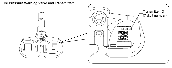

      1. Take note of the 7-digit number (transmitter ID) written on the tire pressure warning valve and transmitter.


        E128762E11

      NOTICE:
      The transmitter ID is written on the tire pressure warning valve and transmitter. It will be unable to be read after installing the tire onto the wheel. Therefore, take note of the transmitter ID before installing the tire onto the wheel.


REGISTER TRANSMITTER ID (USING TECHSTREAM) (Tire Pressure Warning System)
  1. Set the air pressure of all tires to the specified value (Click here).

  2. Turn the ignition switch off.

  3. Connect Techstream to the DLC3.

  4. Turn the ignition switch on (IG) and turn the tester ON.

  5. Enter the menu items in this order: Chassis / Tire Pressure Monitor / Utility / ID Registration.

  6. Perform the following procedures displayed on the screen.

  7. Confirmation of transmitter ID registration.

    1. Enter the menu items in this order: Chassis / Tire Pressure Monitor / Data List.

    2. Read the "ID Tire Inflation Pressure" values.

    3. Confirm that the data of tire pressure of all tires are displayed on the screen.

      NOTICE:
      1. It may take up to about 2 or 3 minutes to update the tire pressure data. If the values are not displayed after a few minutes, perform troubleshooting according to the inspection procedure for DTCs C2121/21 to C2125/25 (Click here).
      2. If the IDs have not been registered, DTC C2171/71 is set in the tire pressure warning ECU after 3 minutes or more.
      3. If normal pressure values are displayed, the IDs have been registered correctly.
      4. If the tire pressure values are not displayed after several minutes, the IDs may be incorrect or the system may have a malfunction.
      5. After all IDs are registered, DTC C2126/26 (Transmitter ID not Received in Main Mode) is set in the tire pressure warning ECU and the tire pressure warning light blinks for 1 minute and then comes on. When the tire pressure warning ECU successfully receives radio waves from all the transmitters whose IDs are stored in the ECU, DTC C2126/26 is deleted and the tire pressure warning light goes off.


INITIALIZATION PROCEDURE (Tire Pressure Warning System)
  1. Turn the ignition switch on (IG).


  2. Press and hold the tire pressure warning reset switch for 3 seconds or more so that the tire pressure warning light blinks 3 times.
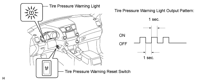

    C157685E01

  3. Turn the ignition switch off.

  4. Connect Techstream to the DLC3.

  5. Enter the following menus: Chassis / Tire Pressure Monitor / Data List.

  6. Check that the initialization has been completed.

  7. Confirm that the tire pressure data of all tires are displayed on the tester screen.

    NOTICE:
    1. The initialization is normally completed within 2 to 3 minutes.
    2. If the initialization has not been completed successfully, DTC C2177/77 will be set after the vehicle is driven for 20 minutes or more.
    3. The initialization can be terminated by connecting terminals TC and CG of the DLC3.


Tire Pressure Monitor 
Tester Display
Measurement Item/Range
Normal Condition
Diagnostic Note
ID1 Tire Inflation Pressure
ID1 tire inflation pressure/
min.: Absolute pressure / 0 kPa (0 kgf/cm2, 0 psi), Relative pressure / -100 kPa (-1.0 kgf/cm2, -14 psi)
max.: Absolute pressure / 637.5 kPa (6.5 kgf/cm2, 92.5 psi), Relative pressure / 537.5 kPa (5.4 kgf/cm2, 78 psi)
Actual tire inflation pressure
If 0 kPa (0 kgf/cm2, 0 psi) is displayed for absolute pressure or -100 kPa (-1.0 kgf/cm2, -14 psi) is displayed for relative pressure, data has not been received.*
ID2 Tire Inflation Pressure
ID2 tire inflation pressure /
min.: Absolute pressure / 0 kPa (0 kgf/cm2, 0 psi), Relative pressure / -100 kPa (-1.0 kgf/cm2, -14 psi)
max.: Absolute pressure / 637.5 kPa (6.5 kgf/cm2, 92.5 psi), Relative pressure / 537.5 kPa (5.4 kgf/cm2, 78 psi)
Actual tire inflation pressure
If 0 kPa (0 kgf/cm2, 0 psi) is displayed for absolute pressure or -100 kPa (-1.0 kgf/cm2, -14 psi) is displayed for relative pressure, data has not been received.*
ID3 Tire Inflation Pressure
ID3 tire inflation pressure /
min.: Absolute pressure / 0 kPa (0 kgf/cm2, 0 psi), Relative pressure / -100 kPa (-1.0 kgf/cm2, -14 psi)
max.: Absolute pressure / 637.5 kPa (6.5 kgf/cm2, 92.5 psi), Relative pressure / 537.5 kPa (5.4 kgf/cm2, 78 psi)
Actual tire inflation pressure
If 0 kPa (0 kgf/cm2, 0 psi) is displayed for absolute pressure or -100 kPa (-1.0 kgf/cm2, -14 psi) is displayed for relative pressure, data has not been received.*
ID4 Tire Inflation Pressure
ID4 tire inflation pressure /
min.: Absolute pressure / 0 kPa (0 kgf/cm2, 0 psi), Relative pressure / -100 kPa (-1.0 kgf/cm2, -14 psi)
max.: Absolute pressure / 637.5 kPa (6.5 kgf/cm2, 92.5 psi), Relative pressure / 537.5 kPa (5.4 kgf/cm2, 78 psi)
Actual tire inflation pressure
If 0 kPa (0 kgf/cm2, 0 psi) is displayed for absolute pressure or -100 kPa (-1.0 kgf/cm2, -14 psi) is displayed for relative pressure, data has not been received.*
ID5 Tire Inflation Pressure
ID5 tire inflation pressure /
min.: Absolute pressure / 0 kPa (0 kgf/cm2, 0 psi), Relative pressure / -100 kPa (-1.0 kgf/cm2, -14 psi)
max.: Absolute pressure / 637.5 kPa (6.5 kgf/cm2, 92.5 psi), Relative pressure / 537.5 kPa (5.4 kgf/cm2, 78 psi)
Actual tire inflation pressure
If 0 kPa (0 kgf/cm2, 0 psi) is displayed for absolute pressure or -100 kPa (-1.0 kgf/cm2, -14 psi) is displayed for relative pressure, data has not been received.*

HINT:
  1. The initialization is complete when the DATA LIST "ID Tire Inflation Pressure" display shows the correct pressures.
  2. *: It may take about 2 or 3 minutes until the values are displayed. If the values are not displayed after a few minutes, perform troubleshooting according to the inspection procedure for DTCs C2121/21 to C2125/25 (Click here).


OBTAIN ZERO POINT OF YAW RATE AND ACCELERATION SENSOR (When Using Techstream) (Vehicle Stability Control System)

NOTICE:
  1. While obtaining the zero points, keep the vehicle stationary and do not vibrate, tilt, move, or shake it. (Do not start the engine.)
  2. Be sure to perform this procedure on a level surface (with an inclination of less than 1 degree).

  1. Clear the zero point calibration data.

    1. Turn the ignition switch off.

    2. Check that the steering wheel is in the straight-ahead position.

    3. Check that the shift lever is in the P position.

    4. Connect Techstream to the DLC3.

    5. Turn the ignition switch on (IG).

    6. Turn Techstream on.

    7. Select the skid control ECU to clear the zero point calibration data using Techstream. Enter the following menus: Chassis / ABS/VSC/TRAC / Utility / Reset Memory.

    8. Turn the ignition switch off.

      NOTICE:
      If the ignition switch is turned on (IG) for more than 15 seconds with the shift lever in the P position after the zero points of the yaw rate and acceleration sensor have been cleared, only the zero point of the yaw rate sensor will be stored. If the vehicle is driven under these conditions, the skid control ECU will store the zero point calibration for the acceleration sensor as not being completed. The skid control ECU will then also indicate this as a malfunction of the VSC system using the indicator lights.


  2. Perform the zero point calibration of the yaw rate and acceleration sensor.

    1. Turn the ignition switch off.

    2. Check that the steering wheel is in the straight-ahead position.

    3. Check that the shift lever is in the P position.

      NOTICE:
      DTCs C1210 (zero point calibration of yaw rate sensor undone) and C1336 (zero point calibration of acceleration sensor undone) will be recorded if the shift lever is not in the P position.

    4. Connect Techstream to the DLC3.

    5. Turn the ignition switch on (IG).

    6. Turn Techstream on.

    7. Switch the skid control ECU to Test Mode using Techstream. Enter the following menus: Chassis / ABS/VSC/TRAC / Utility / Test Mode.

    8. After Test Mode has been entered, keep the vehicle stationary on a level surface for 2 seconds or more.
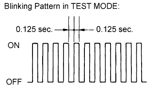


    9. BR03904E80
    10. Check that the slip indicator light comes on for several seconds and then blinks in Test Mode.

      HINT:
      1. The TRAC OFF indicator light remains on during Test Mode because TRAC is prohibited.
      2. If the slip indicator light does not blink, perform zero point calibration again.
      3. The zero point calibration is performed only once after the system enters Test Mode.
      4. Calibration cannot be performed again until the stored data is cleared.

    11. Turn the ignition switch off and disconnect Techstream.


OBTAIN ZERO POINT OF YAW RATE AND ACCELERATION SENSOR (When not Using Techstream) (Vehicle Stability Control System)

NOTICE:
  1. While obtaining the zero points, keep the vehicle stationary and do not vibrate, tilt, move, or shake it. (Do not start the engine.)
  2. Be sure to perform this procedure on a level surface (with an inclination of less than 1 degree).


  1. Clear the zero point calibration data.

    1. Turn the ignition switch off.

    2. Check that the steering wheel is in the straight-ahead position.

    3. Check that the shift lever is in the P position.

    4. Turn the ignition switch on (IG).

    5. The warning light and indicator light come on for 3 seconds to indicate that the initial check is completed.
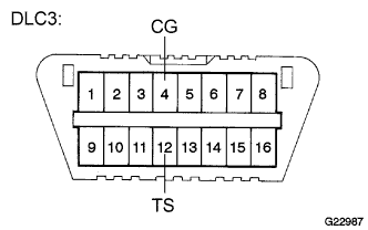


    6. G022987E45
    7. Using SST, connect and disconnect terminals TS and CG of the DLC3 4 times or more within 8 seconds.

      SST
      09843-18040  

    8. Check that the slip indicator light comes on.

      NOTICE:
      If the ignition switch is turned on (IG) for more than 15 seconds with the shift lever in the P position after the zero points of the yaw rate and acceleration sensor have been cleared, only the zero point of the yaw rate sensor will be stored. If the vehicle is driven under these conditions, the skid control ECU will store the zero point calibration for the acceleration sensor as not being completed. The skid control ECU will then also indicate this as a malfunction of the VSC system using the indicator lights.


  2. Perform the zero point calibration of the yaw rate and acceleration sensor.

    1. Turn the ignition switch off.

    2. Check that the steering wheel is in the straight-ahead position.

    3. Check that the shift lever is in the P position.

      NOTICE:
      DTCs 36 (zero point calibration of yaw rate sensor undone) and 39 (zero point calibration of acceleration sensor undone) will be recorded if the shift lever is not in the P position.


    4. G022987E45
    5. Using SST, connect terminals TS and CG of the DLC3.

      SST
      09843-18040  

    6. Turn the ignition switch on (IG).

    7. After Test Mode has been entered, keep the vehicle stationary on a level surface for 2 seconds or more.


    8. BR03904E80
    9. Check that the slip indicator light comes on for several seconds and then blinks in Test Mode.

      HINT:
      1. The TRAC OFF indicator light remains on during Test Mode because TRAC is prohibited.
      2. If the slip indicator light does not blink, perform zero point calibration again.
      3. The zero point calibration is performed only once after the system enters Test Mode.
      4. Calibration cannot be performed again until the stored data is cleared.

    10. Turn the ignition switch off and disconnect SST from the DLC3.


ZERO POINT CALIBRATION (Occupant Classification System)
  1. Zero point calibration procedures

    HINT:
    Make sure that the zero point calibration has finished normally, and then perform the sensitivity check.


    1. Check that all of the following conditions are met:

      1. The vehicle is parked on a level surface.
      2. No objects are placed on the front passenger seat.
      3. The front passenger seat belt buckle switch is OFF.

    2. Adjust the seat position according to the table below.
      Adjustment Item
      Position
      Slide Direction
      Rearmost position
      Reclining Angle
      Upright position
      Headrest Height
      Lowest position
      Lifter Height
      Lowest position

    3. Turn the ignition switch off.

    4. Connect Techstream to the DLC3.

    5. Turn the ignition switch on (IG) and turn the Techstream on.

    6. Enter the following menus: Body Electrical / Occupant Detection / Utility / Zero Point Calibration.

    7. Perform the zero point calibration by following the prompts on the Techstream screen.

      HINT:
      1. Refer to the Techstream operator's manual for further details.
      2. If the zero point calibration does not complete, replace the front seat assembly RH.

      OK:
      "Zero Point calibration is complete." is displayed.


SENSITIVITY CHECK (Occupant Classification System)
  1. Sensitivity check procedures

    1. Turn the ignition switch off.

    2. Connect Techstream to the DLC3.

    3. Turn the ignition switch on (IG) and turn the Techstream on.

    4. Enter the following menus: Body Electrical / Occupant Detection / Utility / Sensitivity Check.

    5. Perform the sensitivity check by following the prompts on the Techstream screen.

      HINT:
      Refer to the Techstream operator's manual for further details.

    6. Confirm that the initial sensor reading is within the specified range.

      Standard:
      -3.2 to 3.2 kg (-7 to 7 lb)

    7. Place a 30 kg (66.14 lb) weight (eg. a 30 kg (66.14 lb) of lead mass) onto the front passenger seat.

    8. Confirm that the sensitivity is within the specified range.

      Standard:
      27 to 33 kg (59.52 to 72.75 lb)

      HINT:
      1. When performing the sensitivity check, use a solid metal weight (the check result may not appear properly if a liquid weight made from liquid is used).
      2. If the sensitivity deviates from the specified range, retighten the bolts of the front passenger seat without deforming the seat rail. After performing this procedure, if the sensitivity is not within the specified range, replace the front seat assembly RH.


REGISTRATION OF RECOGNITION CODE (USING TECHSTREAM) (Wireless Door Lock Control System (w/o Smart key System))

HINT:
For detailed procedures, refer to the prompts on the tester screen. The number of currently registered codes can be checked out on the first screen of the WIRELESS REGIST.

  1. Turn the ignition switch to the ON position.

  2. Enter the following menus: Body Electrical / Main Body / Wireless Registration.

  3. Press both LOCK and UNLOCK switches within 1 to 1.5 seconds.

  4. Press either switch for more than 1 second within 3 seconds.


  5. Check the response to the registration completion.
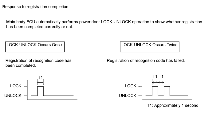

    B111915E15

    HINT:
    1. If the LOCK-UNLOCK operation occurs twice, the registration of recognition code has failed. Perform the registration procedures again from the beginning.
    2. If registering another transmitter, repeat the procedures after the tester operation. All 6 recognition codes can be registered consecutively.

  6. Perform either of the following to complete the registration of recognition codes:

    1. Use Techstream to send completion command.
    2. Disconnect Techstream.


REGISTER RECOGNITION CODE (USING SWITCH OPERATION) (Wireless Door Lock Control System (w/o Smart key System))
  1. The following conditions should be met.

    1. No key in the ignition key cylinder.
    2. The driver side door is open (the other doors are closed).
    3. The driver side door is unlocked.

  2. Insert and remove the key into / from the ignition key cylinder twice (Insert → Remove → Insert → Remove) within 5 seconds.

    HINT:
    The procedure should end with the key removed.

  3. Perform the following operations within 40 seconds.

    1. Close and open the driver side door twice (Close → Open → Close → Open).

      HINT:
      The procedure should end with the door open.

    2. Insert and remove the key into / from the ignition key cylinder (Insert → Remove).

      HINT:
      The procedure should end with the key removed.

    3. Close and open the driver side door twice (Close → Open → Close → Open).

      HINT:
      The procedure should end with the door open.

    4. Insert the key into the ignition key cylinder and close all doors.


  4. Perform the following operations within 40 seconds.


    1. Turn the ignition switch from ON to OFF at approximately 1 second intervals, operate the ignition switch according to the number of times shown below.
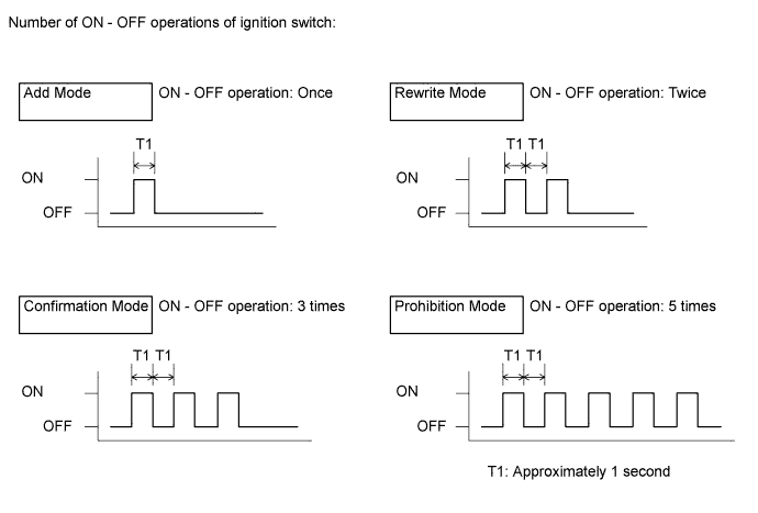

      B111914E11

      HINT:
      If the number of ignition switch ON - OFF operations is 0, 4, 6 or more, there will be no response (the power door lock and unlock operation) to show which mode has been selected.

    2. Remove the key from the ignition key cylinder.


  5. Check the response of the selected mode within 5 seconds.
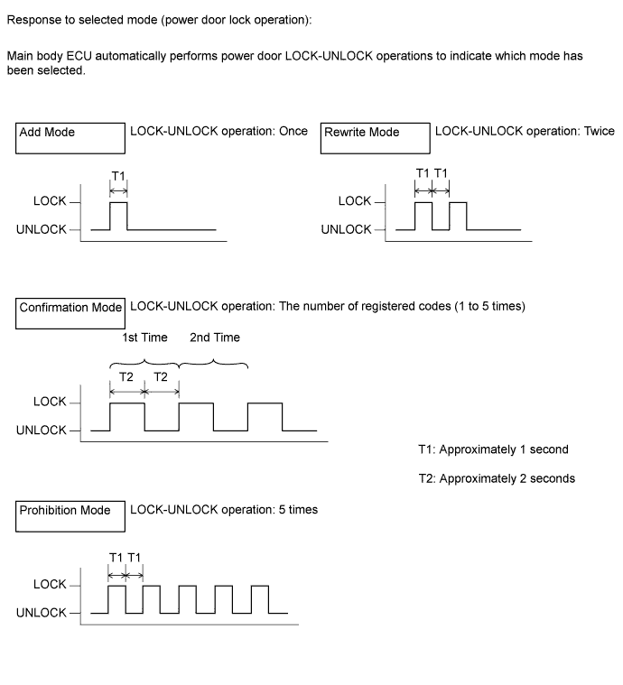

    B111913E11

    NOTICE:
    After the system has been set to the prohibition mode, enter the confirmation mode and check that the number of registered keys is 0.

    HINT:
    1. In the confirmation mode, LOCK-UNLOCK operation will occur once for each recognition code that has been registered. For example, if 2 recognition codes have been registered, LOCK-UNLOCK operation will occur twice.
    2. In the confirmation mode, if no recognition codes have been registered, LOCK-UNLOCK operation will occur 5 times.
    3. If confirmation mode or prohibition mode is selected, the operation ends after the response to the selected mode completes.

  6. Within 40 seconds of completing the confirmation mode operation, press the LOCK and UNLOCK switches on the transmitter simultaneously.

  7. After completing the above step, press a single switch (LOCK or UNLOCK) within 5 seconds.


  8. After completing the above step, check the response to the registration completion within 3 seconds.
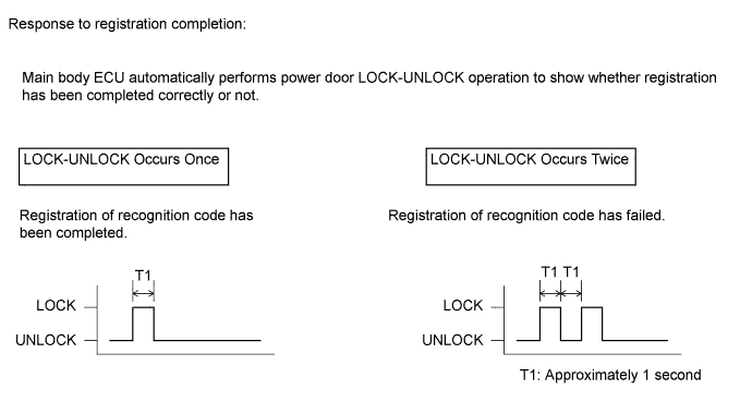

    B111915E16

    HINT:
    1. If the LOCK-UNLOCK operation occurs twice, the registration of recognition code has failed. Perform registration procedures again from the beginning.
    2. If registering another transmitter, repeat the procedures after the response to the selected mode confirmation. All 6 recognition codes can be registered consecutively.

  9. Perform either of the following to complete the registration of recognition codes:

    1. Open the door.
    2. Insert the key into the ignition key cylinder.


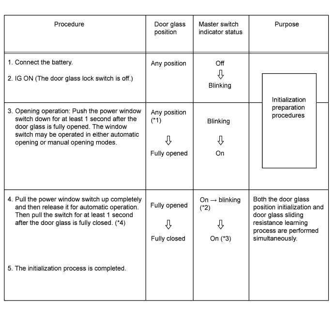
INITIALIZE POWER WINDOW CONTROL SYSTEM (POWER WINDOW REGULATOR MOTOR ASSEMBLY (ON DRIVER SIDE)) (Power Window Control System)
If the initialization procedure cannot be completed normally, there may be a malfunction in the Local Interconnect Network (LIN) communication. Check the body multiplex (LIN, Local Interconnect Network) communication system.

NOTICE:
  1. DTC B2313 will be set if the driver side power window regulator motor assembly is replaced with a new assembly. Clear the DTC after initializing the power window motor.
  2. Initialization should be made when the vehicle is stationary.
  3. Be sure to initialize the door glass position memory (pulse sensor) after replacing the driver side power window regulator motor assembly. Without the initialization, the driver door auto up-and-down function, jam protection function and key-off operation will not work.
  4. Be sure not to tap or give any shock or force to the door glasses during the initialization procedure as the vehicle is learning the door glasses' sliding resistance during initialization.
  5. After replacing the driver side power window regulator, door glass, or glass adhesive dams, be sure to initialize the door glass position memory (pulse sensor). Otherwise, the jam protection function may work when unnecessary.


  1. Inspection procedure


    B175247E01

    HINT:
    1. *1: Even if the door glass has been fully opened before procedure No. 3, it is necessary to press the power window switch down for at least 1 second.
    2. *2: As soon as the switch is pulled completely up (Automatic Closing), the master switch indicator starts to blink.
    3. *3: If the master switch indicator does not come on after procedure No. 4, restart from procedure No. 3.
    4. *4: Allow the automatic operation to continue without stopping until the door glass is fully closed.

    Check the body multiplex (LIN, Local Interconnect Network) system (Click here).


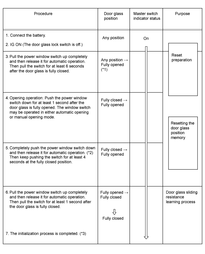
TO RETURN THE SYSTEM TO THE PRE-INITIALIZED CONDITION

NOTICE:
After replacing or reinstalling the driver side power window regulator, door glass, or door glass adhesive dams, be sure to initialize the door glass position memory (pulse sensor). Otherwise, the jam protection function may work when unnecessary.


  1. Procedure


    B175248E01

    HINT:
    1. *1: Even if the door glass has been fully closed before procedure No. 3, it is necessary to pull the power window switch up for at least 6 seconds while the door glass is fully closed.
    2. *2: After completing procedure No. 4, return the door glass switch to its neutral position, then perform automatic opening operation.
    3. *3: After completing the whole initialization process, make sure that the door glass fully closes with the automatic closing operation.
    4. If the initialization procedure cannot be completed normally, there may be a malfunction in the Local Interconnect Network (LIN) communication. Check the body multiplex (LIN, Local Interconnect Network) communication system (Click here).


RESET BACK DOOR CLOSE POSITION (Power Back Door System)
  1. When disconnecting the cable from the battery terminal, fully close the back door to turn off the courtesy switch.

    HINT:
    If the back door is closed when disconnecting the cable from the battery terminal, it is not necessary to reset it.


INITIALIZE SLIDING ROOF DRIVE GEAR SUB-ASSEMBLY (Sliding Roof System)

NOTICE:
Be sure to initialize the sliding roof drive gear (pulse sensor) after adjusting the sliding roof glass position or removing and installing components. Without initialization, there may be a malfunction in the sliding roof auto operation, or key-off operation.
If any of the following conditions occurs during initialization procedure, initialization will fail.
  1. The ignition switch is turned off.
  2. Communication is cut off.
  3. Another switch is turned on during initialization.
  4. Vehicle speed is 5 km/h (3 mph) or more.
  5. The vehicle experiences a strong vibration during initialization, such as the slamming of a door.

  1. Initialization

    HINT:
    According to the following chart, proceed to the appropriate initialization procedure.


    Sliding Roof Condition
    Proceed to
    The sliding roof AUTO function does not operate.
    [A]
    The sliding roof AUTO function
    [B]
    Although the sliding roof AUTO function operates, the roof glass stops moving or starts moving in the opposite direction while tilting downward.
    [B]
    Although the sliding roof AUTO function operates, the roof glass stops moving or starts moving in the opposite direction while sliding closed.
    [C]

    1. [A] The sliding roof AUTO function does not operate.

      1. Turn the ignition switch on (IG). *1
      2. Fully close the sliding roof.
      3. Press and hold the sliding roof switch (TILT UP side) until the following movement finishes: Tilt up → stationary state for at least 1 second → tilt down → slide open → slide close.

        NOTICE:
        Press and hold the sliding roof switch (TILT UP side) until step *2 is complete. If the switch is released before step *2 is complete, restart from step *1.

      4. Confirm that the roof glass is stopped at the fully closed position and initialization is completed. *2

    2. [B] Although the sliding roof AUTO function operates, the roof glass stops moving or starts moving in the opposite direction while tilting downward.

      1. Turn the ignition switch on (IG). *1
      2. Press and hold the sliding roof switch (TILT UP side) until the sliding roof stops.
      3. After the sliding roof stops, release the switch.
      4. Press and hold the sliding roof switch (TILT UP side) for more than 10 seconds until the following movement finishes: Tilt up → stationary state for at least 1 second → tilt down → slide open → slide close.

        NOTICE:
        Press and hold the sliding roof switch (TILT UP side) until step *2 is complete. If the switch is released before step *2 is complete, restart from step *1.

      5. Confirm that the roof glass is stopped at the fully closed position and initialization is complete. *2
      6. Confirm that the sliding roof can be normally operated with the AUTO function.

    3. [C] Although the sliding roof AUTO function operates, the roof glass stops moving or starts moving in the opposite direction while sliding closed.

      1. Turn the ignition switch on (IG). *1
      2. Press and hold sliding roof switch (TILT UP side) until the following movement finishes: Slide close → roof glass stops moving or starts moving in the opposite direction → stationary for at least 10 seconds → slide close.

        NOTICE:
        Press and hold sliding roof switch (TILT UP side) until step *2 is complete. If the switch is released before step *2 is complete, restart from step *1.

      3. After the sliding roof has stopped at the fully closed position, release the switch. *2
      4. Follow the initialization procedure described in [A] (The sliding roof AUTO function does not function.)