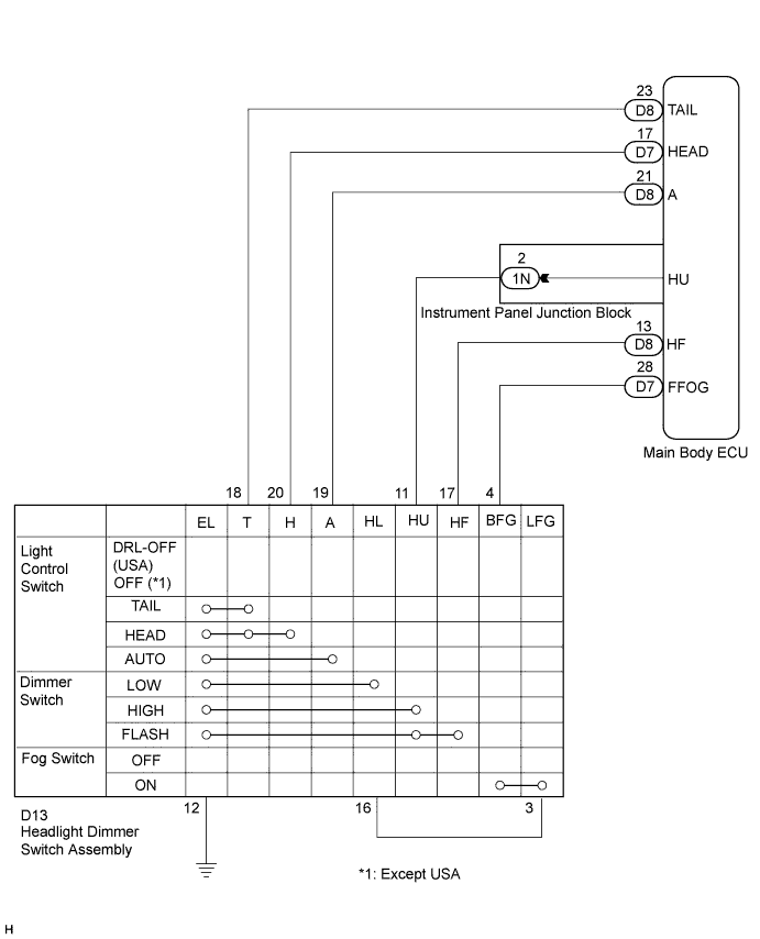
LIGHTING SYSTEM > Light Control Switch Circuit |
| 1.READ VALUE USING TECHSTREAM |
Connect Techstream to the DLC3.
Turn the ignition switch on (IG).
Turn Techstream on.
Select the following menu items: Body Electrical / Main Body / Data List.
Read the display on Techstream.
| Tester Display | Measurement Item/Range | Normal Condition | Diagnostic Note |
| Dimmer Hi SW | Dimmer switch HIGH signal / ON or OFF | ON: Dimmer switch in HIGH or HIGH FLASH OFF: Dimmer switch in LOW | - |
| Passing Light SW | Dimmer switch HIGH FLASH signal / ON or OFF | ON: Dimmer switch in HIGH FLASH OFF: Dimmer switch not in HIGH FLASH | - |
| Front Fog Light SW | Front fog light switch signal / ON or OFF | ON: Fog light switch ON OFF: Fog light switch OFF | - |
| Light Auto SW | Light control switch AUTO signal / ON or OFF | ON: Light control switch in AUTO OFF: Light control switch not in AUTO | - |
| Headlight SW | Light control switch HEAD signal / ON or OFF | ON: Light control switch in HEAD OFF: Light control switch not in HEAD | - |
| Taillight SW | Light control switch TAIL signal / ON or OFF | ON: Light control switch in TAIL or HEAD OFF: Light control switch in neither TAIL nor HEAD | - |
|
| ||||
| OK | ||
 | ||
| ||
| 2.INSPECT HEADLIGHT DIMMER SWITCH ASSEMBLY |
Inspect the headlight dimmer switch assembly (Click here).
|
| ||||
| OK | |
 |
| 3.CHECK HARNESS AND CONNECTOR (INSTRUMENT PANEL JUNCTION BLOCK - SWITCH ASSEMBLY) |
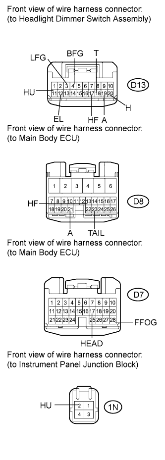 |
Disconnect the D13 headlight dimmer switch assembly connector.
Disconnect the D7 and D8 main body ECU connectors.
Disconnect the 1N instrument panel junction block connector.
Measure the resistance according to the value(s) in the table below.
| Tester Connection | Condition | Specified Condition |
| D13-4 (BFG) - D7-28 (FFOG) | Always | Below 1 Ω |
| D13-11 (HU) - 1N-2 (HU) | Always | Below 1 Ω |
| D13-17 (HF) - D8-13 (HF) | Always | Below 1 Ω |
| D13-18 (T) - D8-23 (TAIL) | Always | Below 1 Ω |
| D13-19 (A) - D8-21 (A) | Always | Below 1 Ω |
| D13-20 (H) - D7-17 (HEAD) | Always | Below 1 Ω |
| D13-3 (LFG) - Body ground | Always | 10 kΩ or higher |
| D13-4 (BFG) - Body ground | Always | 10 kΩ or higher |
| D13-11 (HU) - Body ground | Always | 10 kΩ or higher |
| D13-17 (HF) - Body ground | Always | 10 kΩ or higher |
| D13-18 (T) - Body ground | Always | 10 kΩ or higher |
| D13-19 (A) - Body ground | Always | 10 kΩ or higher |
| D13-20 (H) - Body ground | Always | 10 kΩ or higher |
| D13-12 (EL) - Body ground | Always | Below 1 Ω |
|
| ||||
| OK | ||
| ||
| ||

