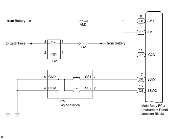
SMART KEY SYSTEM > Power Source Mode does not Change |
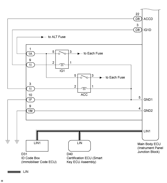
| 1.CHECK SMART KEY SYSTEM |
Remove the battery of the electrical key transmitter (Click here).
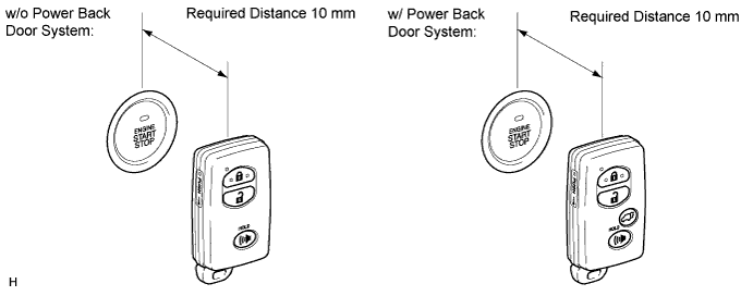
Touch the logo side mark of the key or card key to the engine witch.
Check that the engine switch can be turned on (IG).
| Result | Proceed to |
| Power source mode does not change to on (ACC) | A |
| Power source mode does not change to on (IG) | B |
| Power source mode does not change to on (IG and ACC) | C |
| Power source mode is turned on | D |
|
| ||||
|
| ||||
|
| ||||
| A | |
 |
| 2.INSPECT ACC RELAY |
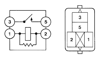 |
Remove the ACC relay from the instrument panel junction block.
Measure the resistance according to the value(s) in the table below.
| Tester Connection | Condition | Specified condition |
| 3 - 5 | When battery voltage is not applied to terminals 1 and 2 | 10 kΩ or higher |
| 3 - 5 | When battery voltage is applied to terminals 1 and 2 | Below 1 Ω |
|
| ||||
| OK | |
|
| 3.CHECK HARNESS AND CONNECTOR (MAIN BODY ECU - INSTRUMENT PANEL JUNCTION BLOCK) |
Disconnect the D8 connector from the main body ECU (instrument panel junction block).
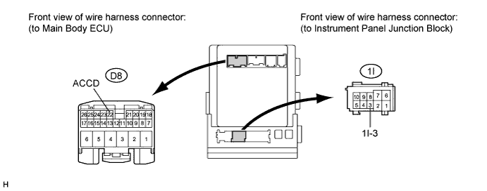
Disconnect the 1I connector from the instrument panel junction block.
Measure the resistance according to the value(s) in the table below.
| Tester Connection | Condition | Specified condition |
| D8-22 (ACCD) - 1I-3 | Always | Below 1 Ω |
| D8-22 (ACCD) or 1I-3 - Body ground | Always | 10 kΩ or higher |
|
| ||||
| OK | ||
 | ||
| ||
| 4.INSPECT IG1 RELAY |
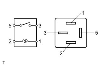 |
Remove the IG1 relay from the instrument panel junction block.
Measure the resistance according to the value(s) in the table below.
| Tester connection | Condition | Specified condition |
| 3 - 5 | When battery voltage is not applied to terminals 1 and 2 | 10 kΩ or higher |
| 3 - 5 | When battery voltage is applied to terminal 1 and 2 | Below 1 Ω |
|
| ||||
| OK | |
|
| 5.CHECK HARNESS AND CONNECTOR (MAIN BODY ECU - INSTRUMENT PANEL JUNCTION BLOCK) |
Disconnect the D8 connector from the main body ECU (instrument panel junction block).
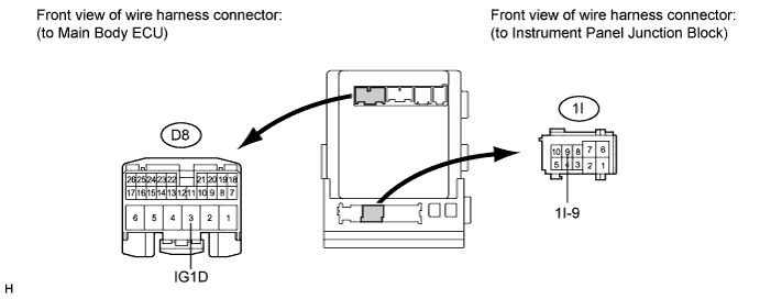
Disconnect the 1I connector from the instrument panel junction block.
Measure the resistance according to the value(s) in the table below.
| Tester connection | Condition | Specified condition |
| D8-3 (IG1D) - 1I-9 | Always | Below 1 Ω |
| D8-3 (IG1D) or 1I-9 - Body ground | Always | 10 kΩ or higher |
|
| ||||
| OK | |
|
| 6.INSPECT IG2 RELAY |
|
Remove the IG2 relay from the engine room relay block.
Measure the resistance according to the value(s) in the table below.
| Tester connection | Condition | Specified condition |
| 3 - 5 | When battery voltage is not applied to terminals 1 and 2 | 10 kΩ or higher |
| 3 - 5 | When battery voltage is applied to terminal 1 and 2 | Below 1 Ω |
|
| ||||
| OK | |
|
| 7.CHECK HARNESS AND CONNECTOR (MAIN BODY ECU - IG2 RELAY) |
Disconnect the D7 connector from the main body ECU (instrument panel junction block).
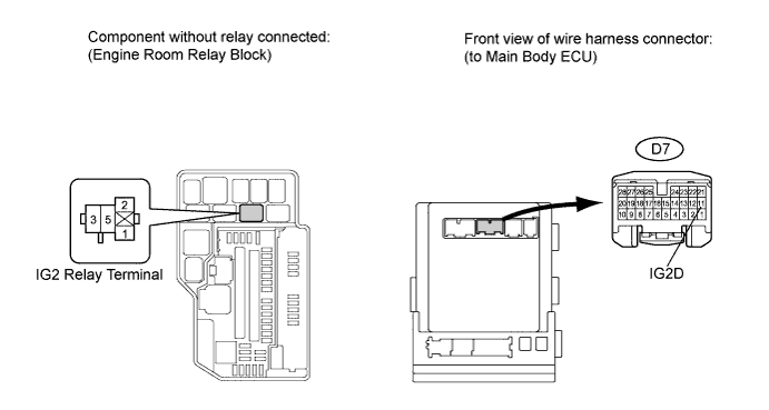
Measure the resistance according to the value(s) in the table below.
| Tester connection | Condition | Specified condition |
| D7-11 (IG2D) - Engine room relay block IG2 relay terminal 1 | Always | Below 1 Ω |
| D7-11 (IG2D) or Engine room relay block IG2 relay terminal 1 - Body ground | Always | 10 kΩ or higher |
|
| ||||
| OK | |
|
| 8.CHECK HARNESS AND CONNECTOR (BATTERY - IG2 RELAY) |
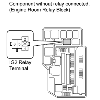 |
Measure the voltage according to the value(s) in the table below.
| Tester connection | Condition | Specified condition |
| Engine room relay block IG2 relay terminal 5 - Body ground | Always | 11 to 14 V |
|
| ||||
| OK | |
|
| 9.CHECK HARNESS AND CONNECTOR (IG2 RELAY - BODY GROUND) |
|
Measure the resistance according to the value(s) in the table below.
| Tester connection | Condition | Specified condition |
| Engine room relay block IG2 relay terminal 2 - Body ground | Always | Below 1 Ω |
|
| ||||
| OK | ||
| ||
| ||
| 10.CHECK HARNESS AND CONNECTOR (BATTERY - INSTRUMENT PANEL JUNCTION BLOCK) |
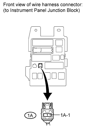 |
Disconnect the 1A connector from the instrument panel junction block.
Measure the voltage according to the value(s) in the table below.
| Tester connection | Condition | Specified condition |
| 1A-1 - Body ground | Always | 11 to 14 V |
|
| ||||
| OK | |
|
| 11.CHECK HARNESS AND CONNECTOR (INSTRUMENT PANEL JUNCTION BLOCK - BODY GROUND) |
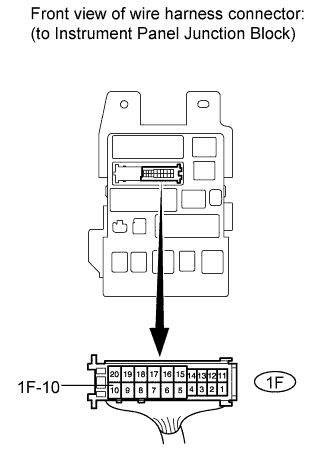 |
Disconnect the 1F connector from the instrument panel junction block.
Measure the resistance according to the value(s) in the table below.
| Tester connection | Condition | Specified condition |
| 1F-10 - Body ground | Always | Below 1 Ω |
|
| ||||
| OK | ||
| ||
| ||

