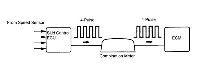
DTC P0500 Vehicle Speed Sensor "A" |
| DTC No. | DTC Detection Condition | Trouble Area |
| P0500 | The ECM detects the following conditions simultaneously for 2 seconds (1 trip detection logic):
|
|
| Related DTCs | P0500: Vehicle speed sensor "A" pulse input error |
| Required Sensors / Components (Main) | Vehicle Speed Sensor (VSS), Combination meter and Skid control ECU |
| Required Sensors / Components (Related) | Park/neutral position switch, engine coolant temperature sensor, crankshaft position sensor and mass air flow meter |
| Frequency of Operation | Continuous |
| Duration | 2 seconds |
| MIL Operation | Immediate |
| Sequence of Operation | None |
| The monitor will run whenever these DTCs are not present | None |
| Time after ignition switch off to on (IG) | 3 seconds or more |
| Engine | Running |
| Transmission counter gear speed | 300 rpm or more |
| Battery voltage | 8 V or more |
| Ignition switch | on (IG) |
| Starter | OFF |
| Either of the following conditions is met | Condition 1 or 2 |
| 1. Both of the following conditions are met | Condition (a) or (b) |
| (a) Engine coolant temperature (P0115, P0117, P0118, P0125) | 20°C (68°F) or more |
| (b) Engine coolant temperature sensor fail | Not detected |
| (c) Time after park/neutral position switch ON to OFF | 2 seconds or more |
| 2. Both of the following conditions are met | Conditions (a) and (b) |
| (a) Engine coolant temperature | Less than 20°C (68°F) |
| (b) Engine coolant temperature sensor fail (P0115, P0117, P0118, P0125) | Detected |
| (c) Time after park/neutral position switch ON to OFF | 30 seconds or more |
| Vehicle speed sensor signal | No signal |
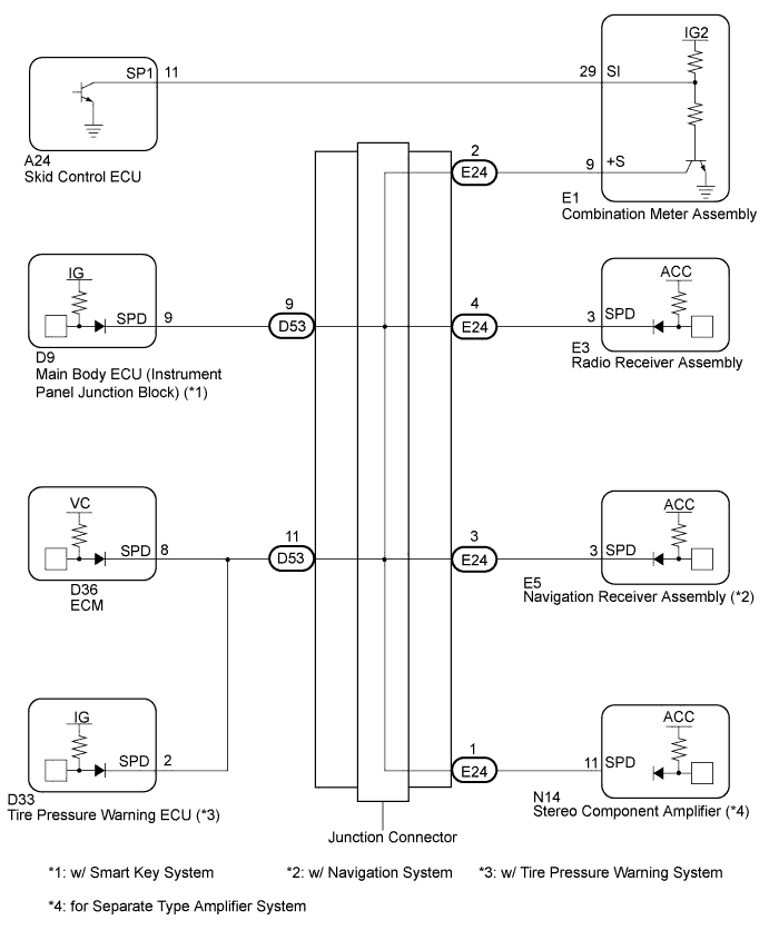
| 1.CHECK HARNESS AND CONNECTOR (COMBINATION METER ASSEMBLY - ECM) |
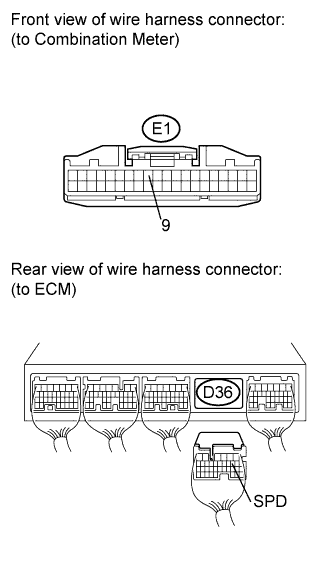 |
Disconnect the combination meter connector.
Disconnect the ECM connector.
Measure the resistance according to the value(s) in the table below.
| Tester Connection | Specified Condition |
| E1-9 - D36-8 (SPD) | Below 1 Ω |
| Tester Connection | Specified Condition |
| E1-9 or D36-8 (SPD) - Body ground | 10 kΩ or higher |
Reconnect the combination meter connector.
Reconnect the ECM connector.
|
| ||||
| OK | |
 |
| 2.INSPECT COMBINATION METER ASSEMBLY (OUTPUT WAVEFORM) |
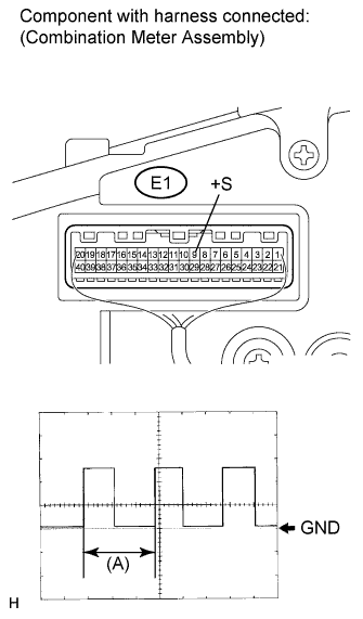 |
Remove the combination meter.
Connect the oscilloscope to terminal E1-9(+S) and body ground.
Turn the ignition switch on (IG).
Turn the wheel slowly.
Check the signal waveform according to the condition(s) in the table below.
| Item | Condition |
| Tool setting | 5 V / DIV., 20 ms / DIV. |
| Vehicle condition | Driving at approx. 20 km/h (12 mph) |
|
| ||||
| OK | ||
 | ||
| ||
| 3.CHECK HARNESS AND CONNECTOR (ECM - JUNCTION CONNECTOR) |
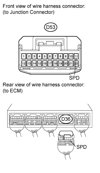 |
Disconnect the ECM connector.
Disconnect the junction connector.
Measure the resistance according to the value(s) in the table below.
| Tester Connection | Condition | Specified Condition |
| D53-11 - D36-8 (SPD) | Always | Below 1 Ω |
Reconnect the ECM connector.
Reconnect the junction connector.
|
| ||||
| OK | ||
| ||
| ||

