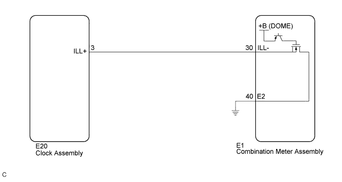
CLOCK SYSTEM > Illumination Circuit |
| w/o Multi-information Display: |
| w/ Multi-information Display: |
| w/o Multi-information Display: |
| w/ Multi-information Display: |
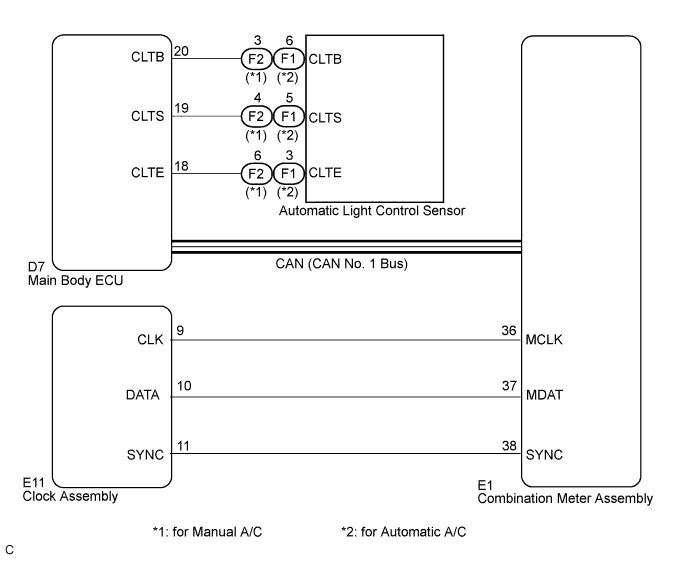
| 1.CONFIRM SYMPTOMS |
Confirm the symptom.
| Result | Proceed to |
| Only clock illumination has a malfunction. | A |
| Clock illumination, combination meter assembly illumination, and heater control panel illumination have a malfunction. | B |
|
| ||||
| A | |
 |
| 2.SYSTEM CHECK |
Confirm the vehicle model.
| Result | Proceed to |
| w/o Multi-information Display | A |
| w/ Multi-information Display | B |
|
| ||||
| A | |
|
| 3.CHECK HARNESS AND CONNECTOR (CLOCK ASSEMBLY - COMBINATION METER) |
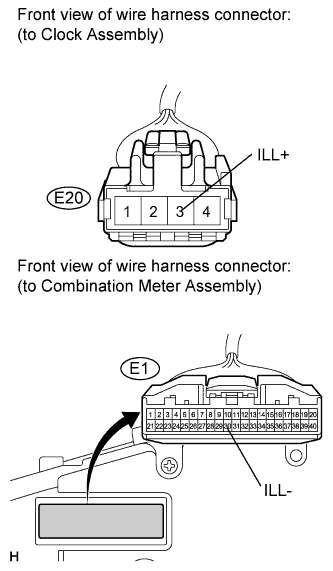 |
Disconnect E1 and E20 connectors.
Measure the resistance according to the value(s) in the table below.
| Tester Connection | Condition | Specified Condition |
| E20-3 (ILL+) - E1-30 (ILL-) | Always | Below 1 Ω |
| E1-30 (ILL-) - Body ground | Always | 10 kΩ or higher |
|
| ||||
| OK | |
|
| 4.INSPECT CLOCK ASSEMBLY |
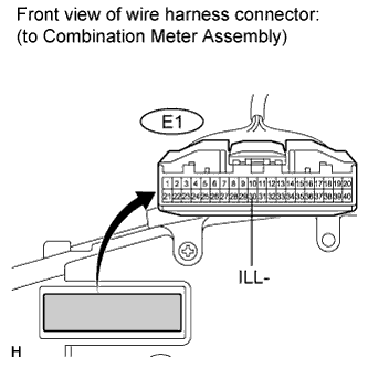 |
Reconnect the E20 connector.
Measure the voltage according to the value(s) in the table below.
| Tester Connection | Condition | Specified Condition |
| E1-30 (ILL-) - Body ground | Ignition switch on (IG), headlight dimmer switch TAIL or HEAD | 11 to 14 V |
| E1-30 (ILL-) - Body ground | Ignition switch on (IG), headlight dimmer switch OFF | Below 1 V |
|
| ||||
| OK | ||
 | ||
| ||
| 5.CHECK CAN COMMUNICATION SYSTEM |
Check if any DTC is output (Click here).
| Result | Proceed to |
| CAN communication DTC is not output. | A |
| CAN Communication DTC is output. | B |
|
| ||||
| A | |
|
| 6.PERFORM ACTIVE TEST USING TECHSTREAM |
Connect Techstream to the DLC3.
Ignition switch on (IG).
Turn the tester ON.
Enter the following menus: Body Electrical / Main Body / Data List.
Check the clock illumination.
| Tester Display | Test Part | Control Range | Diagnostic Note |
| Illumination Rate Info | Illumination rate information / 0 ms. to 99 ms. | 0.8 to 22.0 ms to (Value is output according to outside illuminance) | Confirm that the vehicle is stopped, engine idling |
|
| ||||
| OK | ||
| ||
| ||
| 7.CHECK HARNESS AND CONNECTOR (CLOCK ASSEMBLY - COMBINATION METER) |
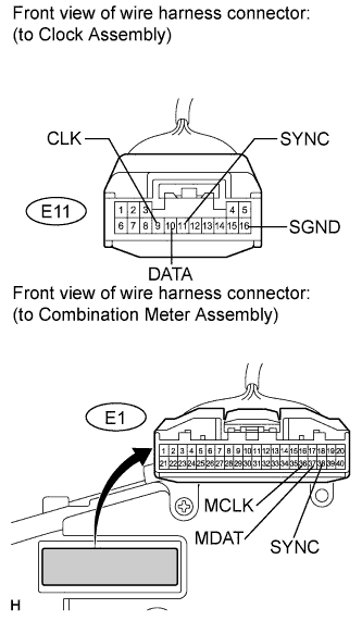 |
Disconnect the E1 and E11 connectors.
Measure the resistance according to the value(s) in the table below.
| Tester Connection | Condition | Specified Condition |
| E11-9 (CLK) - E1-36 (MCLK) | Always | Below 1 Ω |
| E11-10 (DATA) - E1-37 (MDAT) | Always | Below 1 Ω |
| E11-11 (SYNC) - E1-38 (SYNC) | Always | Below 1 Ω |
| E1-36 (MCLK) - Body ground | Always | 10 kΩ or higher |
| E1-37 (MDAT) - Body ground | Always | 10 kΩ or higher |
| E1-38 (SYNC) - Body ground | Always | 10 kΩ or higher |
|
| ||||
| OK | |
|
| 8.INSPECT COMBINATION METER ASSEMBLY |
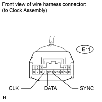 |
Reconnect the E1 connector.
Measure the voltage according to the value(s) in the table below.
| Tester Connection | Condition | Specified Condition |
| E11-9 (CLK) - Body ground | Ignition switch on (IG), headlight dimmer switch TAIL or HEAD | Pulse generation |
| E11-10 (DATA) - Body ground | Ignition switch on (IG), headlight dimmer switch TAIL or HEAD | Pulse generation |
| E11-11 (SYNC) - Body ground | Ignition switch on (IG), headlight dimmer switch TAIL or HEAD | Pulse generation |
| E11-9 (CLK) - Body ground | Ignition switch on (IG), headlight dimmer switch OFF | Below 1 V |
| E11-10 (DATA) - Body ground | Ignition switch on (IG), headlight dimmer switch OFF | Below 1 V |
| E11-11 (SYNC) - Body ground | Ignition switch on (IG), headlight dimmer switch OFF | Below 1 V |
|
| ||||
| OK | ||
| ||
| ||

