 |
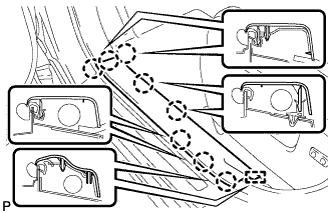
Disengage the 8 claws and guide, and remove the front door scuff plate LH.
POWER STEERING ECU > REMOVAL |
| 1. PRECAUTION |
| 2. PLACE FRONT WHEELS FACING STRAIGHT AHEAD |
| 3. DISCONNECT CABLE FROM NEGATIVE BATTERY TERMINAL |
| 4. REMOVE FRONT DOOR SCUFF PLATE LH |
|
Disengage the 8 claws and guide, and remove the front door scuff plate LH.
| 5. REMOVE COWL SIDE TRIM SUB-ASSEMBLY LH |
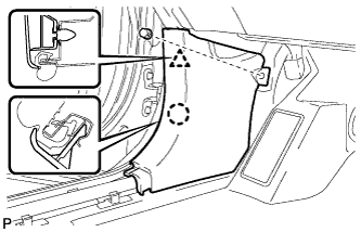 |
Remove the clip.
Disengage the clip and claw, and remove the cowl side trim sub-assembly LH.
| 6. REMOVE LOWER INSTRUMENT PANEL FINISH PANEL SUB-ASSEMBLY (for Manual Air Conditioning System) |
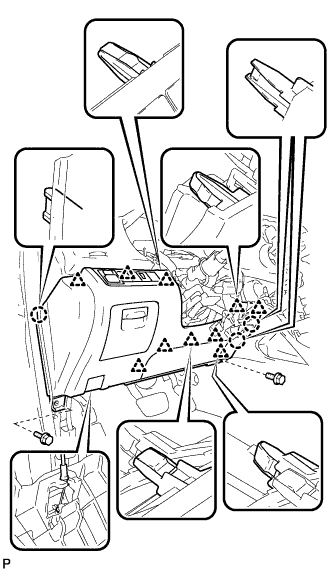 |
Remove the 2 bolts <B>.
Disengage the 3 claws and 10 clips.
Disconnect each connector.
Disconnect the hood lock control cable assembly and remove the lower instrument panel finish panel sub-assembly.
| 7. REMOVE LOWER INSTRUMENT PANEL FINISH PANEL SUB-ASSEMBLY (for Automatic Air Conditioning System) |
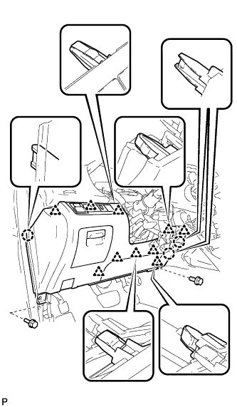 |
Remove the 2 bolts <B>.
Disengage the 3 claws and 10 clips.
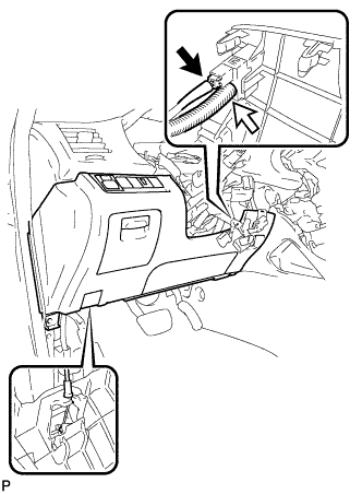 |
Disconnect each connector and the aspirator duct.
Disconnect the hood lock control cable assembly and remove the lower instrument panel finish panel sub-assembly.
| 8. REMOVE DRIVER SIDE KNEE AIRBAG ASSEMBLY |
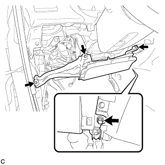 |
Remove the 4 bolts.
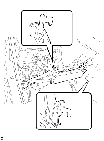 |
Disengage the 2 hooks.
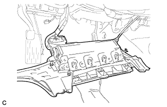 |
Pull out the driver side knee airbag assembly from the vehicle and support the driver side knee airbag assembly with one hand as shown in the illustration.
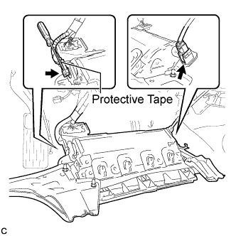 |
Disconnect the tire pressure warning reset switch connector.
Using a screwdriver with the tip wrapped with protective tape, disconnect the driver side knee airbag connector.
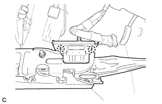 |
Disengage the 2 claws and separate the DLC3 from the driver side knee airbag assembly.
| 9. REMOVE INSTRUMENT PANEL JUNCTION BLOCK ASSEMBLY |
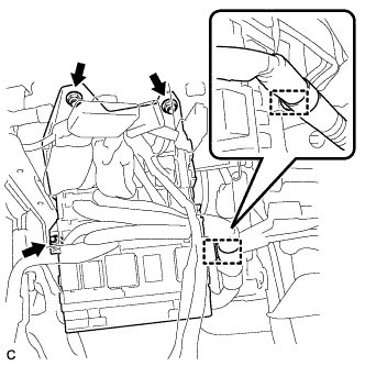 |
Separate the wire harness clamp from the instrument panel junction block assembly.
Disconnect the connectors from the instrument panel junction block assembly.
Remove the 3 nuts.
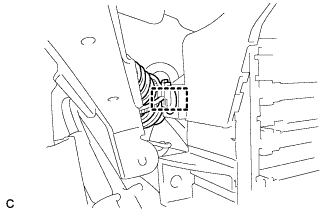 |
Move the instrument panel junction block assembly and disengage the wire harness clamp.
Disconnect the connectors from the back of the instrument panel junction block assembly.
Remove the instrument panel junction block assembly.
| 10. REMOVE POWER STEERING ECU ASSEMBLY |
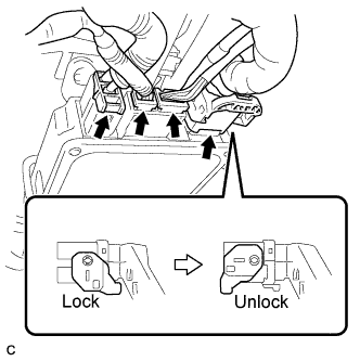 |
Disconnect the 4 connectors from the power steering ECU assembly.
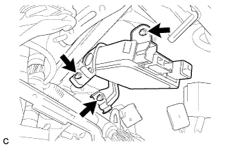 |
Remove the 3 nuts and the power steering ECU assembly.