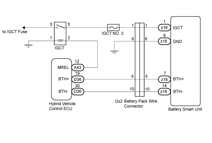
DTC P0A1F-123 Battery Energy Control Module |
| DTC No. | DTC Detection Condition | Trouble Area |
| P0A1F-123 |
|
|
| Related DTCs | P0A1F-123: Range check/Rationality |
| Required sensors/components | Battery smart unit |
| Frequency of operation | Continuous |
| Duration | TOYOTA's intellectual property |
| MIL operation | Immediately or 2 driving cycles |
| Sequence of operation | None |
| The monitor will run whenever the DTCs listed are not present | TOYOTA's intellectual property |
| TOYOTA's intellectual property | - |
| Battery smart unit | DTC P0A1F-123 is not detected |
| 1.CHECK AUXILIARY BATTERY |
Turn the power switch off.
Measure the voltage between the terminals of the auxiliary battery.
| Tester Connection | Condition | Switch Condition | Specified Condition |
| Auxiliary battery positive terminal (+) - Auxiliary battery negative terminal (-) | Battery electrolyte temperature: 68°F (20°C) | Power switch off | 11 to 14 V |
|
| ||||
| OK | |
 |
| 2.CHECK HARNESS AND CONNECTOR (IGCT voltage) |
Turn the power switch on (IG).
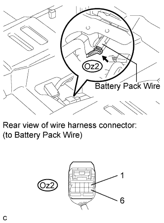 |
Measure the voltage according to the value(s) in the table below.
| Tester Connection | Switch Condition | Specified Condition |
| Oz2-1 - Oz2-6 | Power switch on (IG) | 8.6 V or higher |
|
| ||||
| OK | |
|
| 3.CHECK HARNESS AND CONNECTOR (BATTERY PACK WIRE CONNECTOR - BATTERY SMART UNIT) |
Remove the battery cover (Click here).
Turn the power switch off.
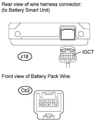 |
Measure the resistance according to the value(s) in the table below.
| Tester Connection | Switch Condition | Specified Condition |
| Oz2-1 - z18-1 (IGCT) | Power switch off | Below 1 Ω |
|
| ||||
| OK | ||
 | ||
| ||
| 4.CHECK FUSE (IGCT NO. 2) |
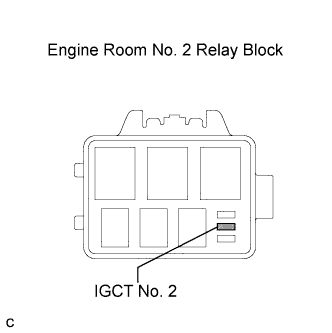 |
Remove the IGCT No. 2 fuse from the engine room No. 2 relay block.
Measure the resistance according to the value(s) in the table below.
| Tester Connection | Condition | Specified Condition |
| IGCT No. 2 fuse | Always | Below 1 Ω |
|
| ||||
| OK | |
|
| 5.CHECK HARNESS AND CONNECTOR (BATTERY PACK WIRE CONNECTOR - IGCT RELAY) |
Disconnect the Oz2 battery pack wire connector.
Install the IGCT No. 2 fuse to the engine room No. 2 relay block.
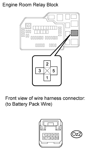 |
Remove the IGCT relay from the engine room relay block.
Measure the resistance according to the value(s) in the table below.
| Tester Connection | Switch Condition | Specified Condition |
| Oz2-1 - IGCT relay terminal 2 | Power switch off | Below 1 Ω |
|
| ||||
| OK | ||
| ||
| ||

