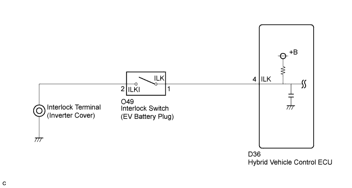
DTC P0A0D-350 High Voltage System Inter-Lock Circuit High |
DTC P0A0D-351 High Voltage System Inter-Lock Circuit High |
| DTC No. | INF Code | DTC Detection Condition | Trouble Area |
| P0A0D | 350 | Operating safety devices with vehicle stopped (ILK signal is ON) |
|
| P0A0D | 351 | Interlock signal circuit opens while the vehicle is being driven at 3 mph (5 km/h) or more |
| 1.CHECK DTC OUTPUT (HV) |
Connect the Techstream to the DLC3.
Turn the power switch on (IG).
Select the following menu items: Powertrain / Hybrid Control / Trouble Codes.
Check if DTCs are output.
| Result | Proceed to |
| P0A1D is not output | A |
| P0A1D is output | B |
|
| ||||
| A | |
 |
| 2.CLEAR DTC |
Turn the power switch on (IG).
Select the following menu items: Powertrain / Hybrid Control / Trouble Codes.
Clear DTCs and freeze frame data.
| NEXT | |
|
| 3.CHECK DTC OUTPUT (HV) |
Turn the power switch on (IG).
Select the following menu items: Powertrain / Hybrid Control / Trouble Codes.
Check if DTCs are output.
| Result | Proceed to |
| P0A0D-350 or P0A0D-351 is output again | A |
| P0A0D-350 or P0A0D-351 is not output again | B |
|
| ||||
| A | |
|
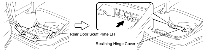
| 4.CHECK SERVICE PLUG GRIP |
Check if the service plug grip is installed correctly.
|
| ||||
| OK | |
|
| 5.CHECK INTERLOCK (INVERTER COVER) |
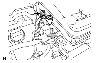 |
Check if the interlock device of the inverter cover is installed correctly.
|
| ||||
| OK | |
|
| 6.INSPECT HYBRID VEHICLE CONTROL ECU |
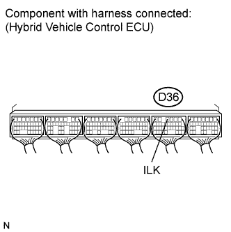 |
Turn the power switch on (IG).
Measure the voltage according to the value(s) in the table below.
| Tester Connection | Switch Condition | Specified Condition |
| D36-4 (ILK) - Body ground | Power switch on (IG) | 9 to 14 V |
|
| ||||
| OK | |
|
| 7.CHECK EV BATTERY PLUG ASSEMBLY |
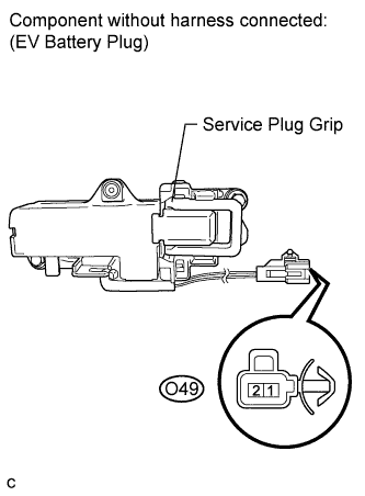 |
Turn the power switch off.
Disconnect the interlock switch connector from the EV battery plug.
Measure the resistance according to the value(s) in the table below.
| Tester Connection | Switch Condition | Specified Condition |
| O49-1 (ILK) - O49-2 (ILKI) | Power switch off | Below 1 Ω |
|
| ||||
| OK | |
|
| 8.CHECK HARNESS AND CONNECTOR (INTERLOCK (INVERTER COVER) - EV BATTERY PLUG) |
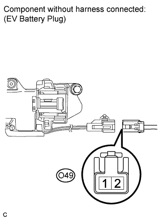 |
Remove the service plug grip (Click here).
Measure the resistance according to the value(s) in the table below.
| Tester Connection | Switch Condition | Specified Condition |
| O49-2 (ILKI)- Body ground | Power switch off | Below 1 Ω |
|
| ||||
| OK | |
|
| 9.CHECK HARNESS AND CONNECTOR (HYBRID VEHICLE CONTROL ECU - EV BATTERY PLUG) |
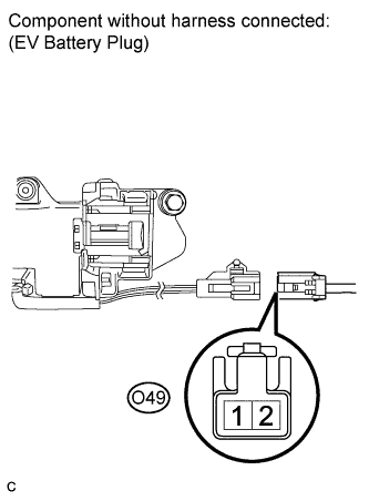 |
Turn the power switch on (IG).
Measure the voltage according to the value(s) in the table below.
| Tester Connection | Switch Condition | Specified Condition |
| O49-1 (ILK)- Body ground | Power switch on (IG) | 9 to 14 V |
|
| ||||
| OK | ||
 | ||
| ||
| 10.CHECK HARNESS AND CONNECTOR (HYBRID VEHICLE CONTROL ECU - EV BATTERY PLUG) |
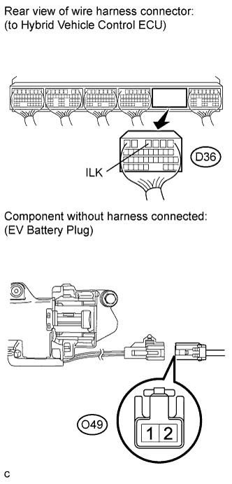 |
Turn the power switch off.
Disconnect the D36 connector from the hybrid vehicle control ECU.
Measure the resistance according to the value(s) in the table below.
| Tester Connection | Switch Condition | Specified Condition |
| D36-4 (ILK) - O49-1 (ILK) | Power switch off | Below 1 Ω |
|
| ||||
| OK | ||
| ||
| ||
| 11.CHECK CONNECTOR CONNECTION CONDITION (INTERLOCK CIRCUIT CONNECTOR) |
Check the connections of each connector.
| Result | Proceed to |
| The connectors are connected securely and there are no contact problems. | A |
| Dirt or foreign objects have entered the connection, or there are remains of them. | B |
|
| ||||
| A | ||
| ||
| ||

