TRANSAXLE CONTROL CABLE ASSEMBLY > INSTALLATION |
| 1. INSTALL TRANSMISSION CONTROL CABLE ASSEMBLY |
In the cabin
![]() |
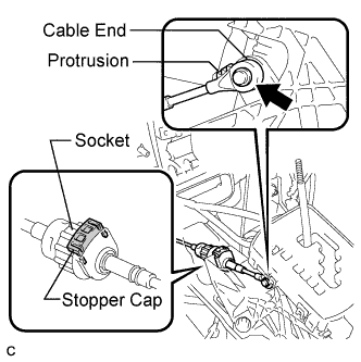
Connect the socket of the transmission control cable assembly to the shift lever assembly.
Connect the control cable end to the shift lever assembly.
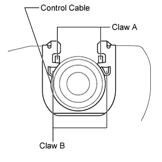
Push the stopper cap to the socket as shown in the illustration.
Turn the socket of the transmission control cable assembly clockwise and install the stopper cap.
![]() |
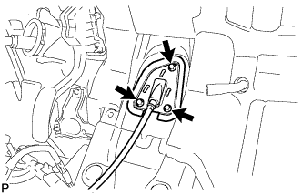
Install the transmission control cable assembly with the 3 bolts.
Move the shift lever to the N position.
In the engine compartment
![]() |
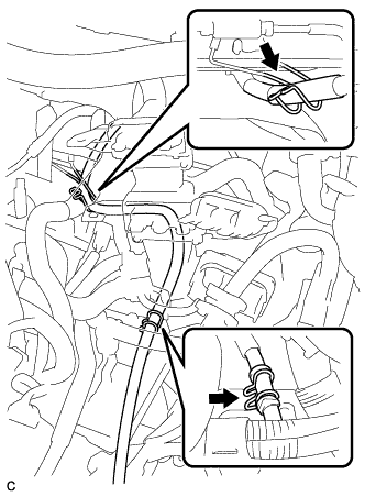
Connect the control cable to the 2 control cable clamps.
Move the control shaft lever to the N position.
Install a new clip to the control bracket.
![]() |
Install the control cable to the control bracket.
![]() |
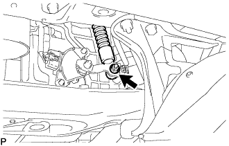
Temporarily install the control cable to the control shaft lever with the nut.
![]() |
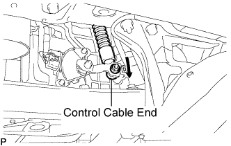
Lightly pull down the control cable end.
Release your hand from the control cable end and then fully tighten the nut.
| 2. INSTALL AIR CONDITIONING UNIT |
| 3. INSTALL NO. 1 INVERTER BRACKET |
![]() |
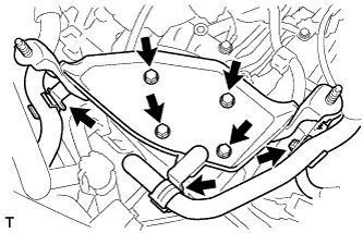
Install the 4 bolts and No. 1 inverter bracket.
Install the harness clamp and hose clamp.
| 4. INSTALL INVERTER WITH CONVERTER ASSEMBLY |
| 5. INSTALL NO. 2 ENGINE ROOM SIDE COVER LH |
![]() |
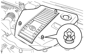
Fit the clips and install the No. 2 engine room side cover LH.
| 6. INSTALL AIR CLEANER CASE SUB-ASSEMBLY |
![]() |
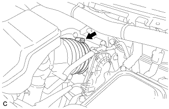
Align the tab on the throttle body with the groove on the air cleaner hose and tighten the hose clamp.
![]() |
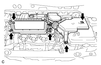
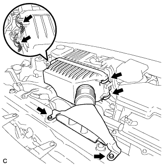
Install the air cleaner case sub-assembly with the 5 bolts.
![]() |
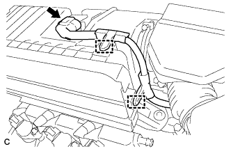
Connect the intake air flow meter connector.
Connect the 2 wire harness clamps to the air cleaner case.
![]() |
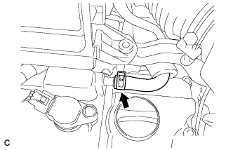
Connect the No. 1 ventilation hose.
| 7. REMOVE AIR CLEANER CAP SUB-ASSEMBLY |
Install the air cleaner filter element to the air cleaner case.
![]() |
Install the 2 bolts, 4 clamps and air cleaner cap sub-assembly.
| 8. INSTALL OUTER COWL TOP PANEL SUB-ASSEMBLY |
![]() |
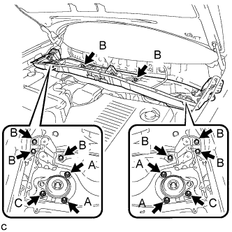
Install the outer cowl top panel sub-assembly with the 8 bolts and 6 nuts.
![]() |
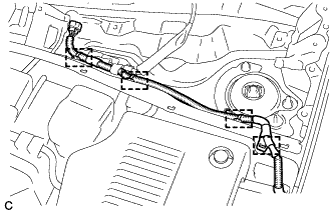
Engage the 4 clamps.
| 9. INSTALL WINDSHIELD WIPER MOTOR AND LINK ASSEMBLY |
![]() |
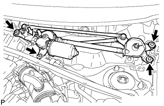
Install the windshield wiper motor and link assembly with the 4 bolts.
Connect the connector.
| 10. INSTALL COWL TOP VENTILATOR LOUVER SUB-ASSEMBLY |
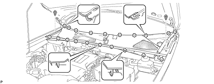
Engage the 20 claws.

Install the cowl top ventilator louver sub-assembly with the 2 clips.
![]() |
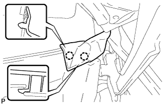
Engage the 2 claws and connect the front fender to cowl side seal LH.
![]() |
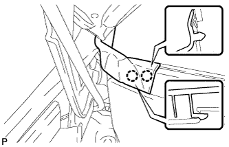
Engage the 2 claws and connect the front fender to cowl side seal RH.
| 11. INSTALL FRONT WIPER ARM AND BLADE ASSEMBLY RH |
Operate the wiper and stop the windshield wiper motor at the automatic stop position.
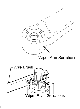
When reinstalling:
![]() |
Clean the wiper arm serrations.
Clean the wiper pivot serrations with a wire brush.
![]() |
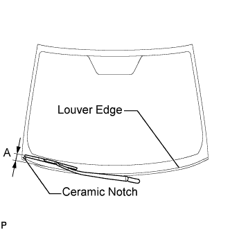
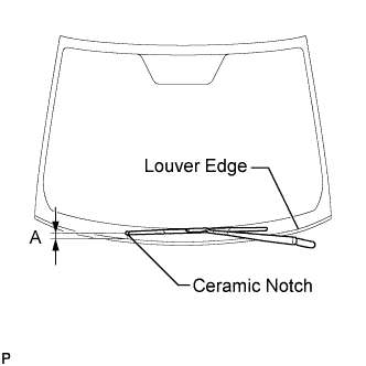
Install the front wiper arm and blade assembly RH with the nut to the position shown in the illustration.
| Area | Measurement |
| A | 25.6 mm (1.00 in.) |
| 12. INSTALL FRONT WIPER ARM AND BLADE ASSEMBLY LH |
Operate the wiper and stop the windshield wiper motor at the automatic stop position.
When reinstalling:
![]() |
Clean the wiper arm serrations.
Clean the wiper pivot serrations with a wire brush.
![]() |
Install the front wiper arm and blade assembly LH with the nut to the position shown in the illustration.
| Area | Measurement |
| A | 31.9 mm (1.26 in.) |
Operate the front wipers while spraying washer fluid onto the windshield glass. Make sure that the front wipers function properly and the wipers do not come into contact with the vehicle body.
| 13. INSPECT SHIFT LEVER POSITION |
Apply the parking brake.
Lock the wheels with chocks to secure the vehicle.
Turn the power switch on (READY).
Move the shift lever to the D position and release the brake pedal.
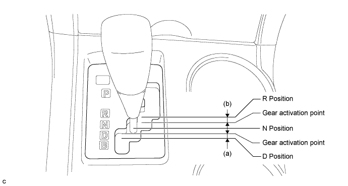
Slowly move the shift lever to the N position and measure moving distance (a) of the shift lever from the original point to the gear activation point.
Move the shift lever to the R position and release the brake pedal.
Slowly move the shift lever to the N position and measure moving distance (b) of the shift lever from the original point to the vehicle activation point.
Check that moving distances (a) and (b) shown in the illustration are almost the same.

| 14. ADJUST SHIFT LEVER POSITION |
If moving distance (a) is shorter than (b) [*1]:

Move the shift lever to the N position.
![]() |
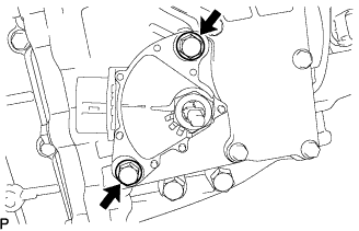
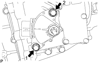
Loosen the 2 bolts.
![]() |
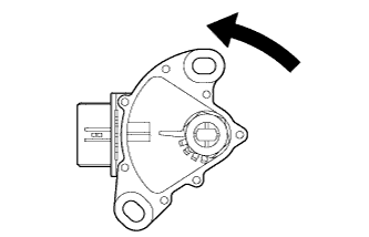
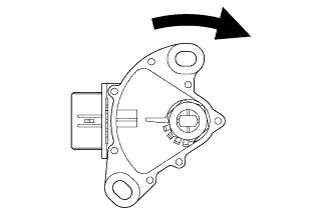
Slightly turn the shift lever position sensor counterclockwise.
![]() |
Tighten the 2 bolts in the order shown in the illustration.
Recheck the shift lever position.
If moving distance (b) is shorter than (a) [*2]:

Move the shift lever to the N position.
![]() |
Loosen the 2 bolts.
![]() |
Slightly turn the shift lever position sensor clockwise.
![]() |
Tighten the 2 bolts in the order shown in the illustration.
Recheck the shift lever position.
| 15. INSPECT SHIFT LEVER OPERATION |
While moving the shift lever from the N to each position, check that the lever moves smoothly and that the shift position indicator comes on properly according to the shift lever position.
Turn the power switch on (READY), and check the following:
When the shift lever is moved to the D position, the vehicle moves forward.
When the shift lever is moved to the R position, the buzzer sounds and the vehicle moves in reverse.
| 16. INSTALL NO. 1 ENGINE UNDER COVER |
Install the 6 bolts, 2 screws, 2 clips and No. 1 engine under cover.