Home › HYBRID SYSTEM ยท P310 › HYBRID VEHICLE CONTROL › INVERTER WITH CONVERTER

INVERTER WITH CONVERTER > INSTALLATION

for Preparation Click here


1. INSTALL INVERTER WITH CONVERTER ASSEMBLY

CAUTION:
Wear insulating gloves.


    A181830
  1. Install the inverter with converter assembly with the 2 nuts and bolt.

    Torque:
    21 N*m{ 214 kgf*cm , 15 ft.*lbf }

    NOTICE:
    1. Since the inverter with converter assembly is very heavy, 2 people are needed to remove the inverter with converter assembly. When removing the inverter with converter assembly, do not damage the parts around it.
    2. To prevent damage, do not hold the inverter with converter assembly by the connectors.
    3. To prevent damage due to static electricity, do not touch the terminals of the disconnected connectors.
2. INSTALL NO. 4 INVERTER BRACKET


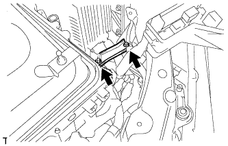
    A181829
  1. Install the No. 4 inverter bracket with the 2 bolts.
    Torque:
    21 N*m{ 214 kgf*cm , 15 ft.*lbf }


3. INSTALL ENGINE ROOM RELAY BLOCK ASSEMBLY

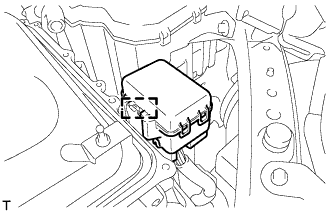
    A181828
  1. Install the engine room relay block assembly.


4. REMOVE INVERTER COVER


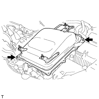
    A181827
  1. Remove the 2 bolts and inverter cover from the inverter with converter assembly.


5. CONNECT NO. 3 FRAME WIRE

CAUTION:
Wear insulating gloves.

NOTICE:
  1. Make sure that the inverter with converter assembly is temporarily installed before working on the inverter with converter assembly (Click here).
  2. Do not allow any foreign objects or waterdrops to enter the inverter with converter assembly.


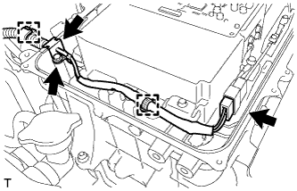
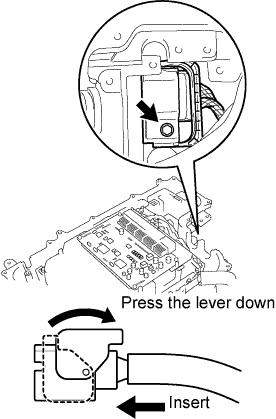
    A109800E01
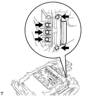
  1. After connecting the connector, press the lever down to connect the No. 3 frame wire and install the bolt to the inverter with converter assembly.

    Torque:
    10 N*m{ 102 kgf*cm , 7 ft.*lbf }

    NOTICE:
    Be sure to use a torque wrench to tighten the bolt.


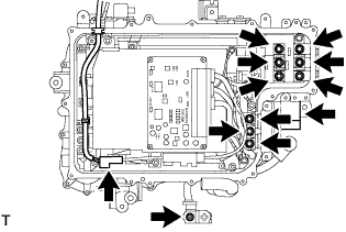
    A108521
  1. Connect the No. 3 frame wire (high voltage cable of the rear motor (MGR)) with new 5 bolts to the inverter with converter assembly.

    Torque:
    10 N*m{ 102 kgf*cm , 7 ft.*lbf }

    NOTICE:
    Make sure that the tightening torque is between 8.0 and 12 N*m (82 and 122kgf*cm, 6 and 9 ft.*lbf).


6. CONNECT MG ECU CONNECTOR

CAUTION:
Wear insulating gloves.

NOTICE:
  1. Make sure that the inverter with converter assembly is temporarily installed before working on the inverter with converter assembly (Click here).
  2. Do not allow any foreign objects or waterdrops to enter the inverter with converter assembly.


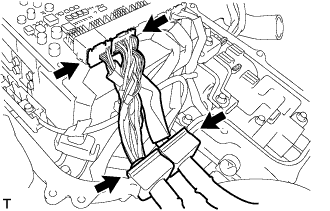
    A108518
  1. Connect the 2 connectors and 2 grommets to the inverter with converter assembly.


7. CONNECT HIGH VOLTAGE CABLE OF FRONT MOTOR

CAUTION:
Wear insulating gloves.

NOTICE:
  1. Make sure that the inverter with converter assembly is temporarily installed before working on the inverter with converter assembly (Click here).
  2. Do not allow any foreign objects or waterdrops to enter the inverter with converter assembly.


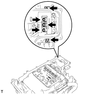
    A108520
  1. Connect the high voltage cable of the generator (MG1) with new 5 bolts to the inverter with converter assembly.

    Torque:
    10 N*m{ 102 kgf*cm , 7 ft.*lbf }

    NOTICE:
    Make sure that the tightening torque is between 8.0 and 12 N*m (82 and 122kgf*cm, 6 and 9 ft.*lbf).


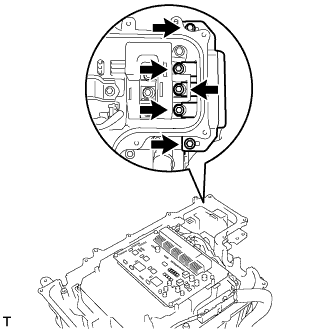
    A108519
  1. Connect the high voltage cable of the motor (MG2) with new 5 bolts to the inverter with converter assembly.

    Torque:
    10 N*m{ 102 kgf*cm , 7 ft.*lbf }

    NOTICE:
    Make sure that the tightening torque is between 8.0 and 12 N*m (82 and 122kgf*cm, 6 and 9 ft.*lbf).


8. CONNECT NO. 4 ENGINE WIRE

CAUTION:
Wear insulating gloves.

NOTICE:
  1. Make sure that the inverter with converter assembly is temporarily installed before working on the inverter with converter assembly (Click here).
  2. Do not allow any foreign objects or waterdrops to enter the inverter with converter assembly.


    A177832
  1. Connect the No. 4 engine wire with the connector, clamp and grommet to the inverter with converter assembly.

  1. Connect the No. 4 engine wire with the bolt to the inverter with converter assembly.

    Torque:
    5.4 N*m{ 55 kgf*cm , 48 in.*lbf }


9. CHECK HIGH VOLTAGE CABLE CONNECTION

CAUTION:
Wear insulating gloves.

NOTICE:
  1. Make sure that the inverter with converter assembly is temporarily installed before working on the inverter with converter assembly (Click here).
  2. Do not allow any foreign objects or waterdrops to enter the inverter with converter assembly.


    A108527
  1. Check that each connector and terminal is firmly installed.

    NOTICE:
    1. Make sure that the connectors are fully engaged.
    2. Make sure that the bolts are fully tightened.


10. INSTALL INVERTER COVER


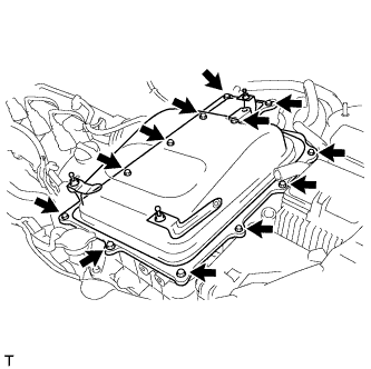
    A181826
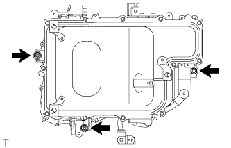
  1. Install the inverter cover with the 12 bolts to the inverter with converter assembly.

    Torque:
    10 N*m{ 102 kgf*cm , 7 ft.*lbf }


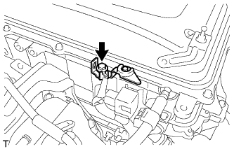
    A175851
  1. Install the interlock bracket with the bolt to the inverter with converter assembly.

    Torque:
    10 N*m{ 102 kgf*cm , 7 ft.*lbf }


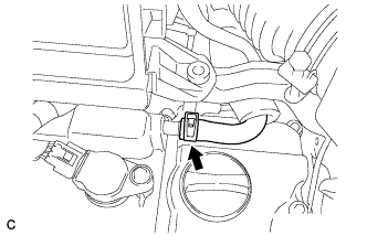
11. CONNECT WATER HOSE


    A181824
  1. Connect the water hose with the clamp to the inverter with converter assembly.


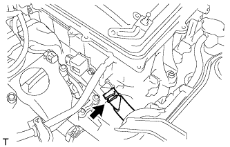
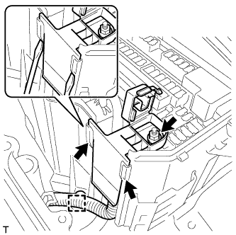
12. CONNECT NO. 2 ENGINE ROOM WIRE


    A175855
  1. Connect the No. 2 engine room wire with the nut.

    Torque:
    8.5 N*m{ 87 kgf*cm , 75 in.*lbf }

  1. Connect the clamp.


    A175854
  1. Install the No. 2 relay block cover with the 4 claws.


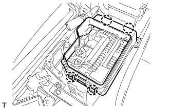
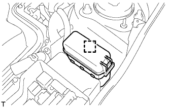
    A175852
  1. Install the engine room relay block assembly.

  1. Install the relay block cover.


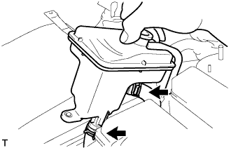
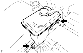
13. INSTALL INVERTER RESERVE TANK SUB-ASSEMBLY


    A108513
  1. Connect the 2 water hoses to the inverter reserve tank sub-assembly with the 2 clamps.


    A108512
  1. Install the inverter reserve tank with the 2 bolts to the inverter with converter assembly.

    Torque:
    10 N*m{ 102 kgf*cm , 7 ft.*lbf }


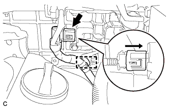
14. CONNECT NO. 1 CIRCUIT BREAKER SENSOR


    A177834
  1. Connect the No. 1 circuit breaker sensor connector.


15. INSTALL AIR CLEANER CASE SUB-ASSEMBLY


    A173490
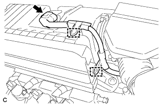
  1. Separate the No. 1 ventilation hose.


    A173491
  1. Disconnect the intake air flow meter connector.

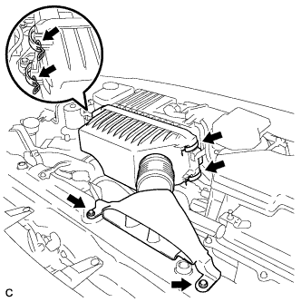
  1. Disconnect the 2 wire harness clamps from the air cleaner case sub-assembly.


    A173492
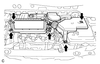
  1. Remove the 5 bolts from the air cleaner case sub-assembly.


    A173493
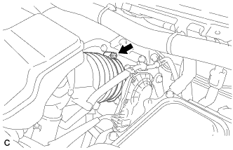
  1. Loosen the hose clamp and separate the No. 1 air cleaner hose.

  1. Remove the air cleaner case sub-assembly.


16. INSTALL AIR CLEANER CAP SUB-ASSEMBLY
  1. Install the air cleaner filter element to the air cleaner case.


    A175875
  1. Install the 2 bolts, 4 clamps and air cleaner cap sub-assembly.

    Torque:
    7.0 N*m{ 71 kgf*cm , 62 in.*lbf }


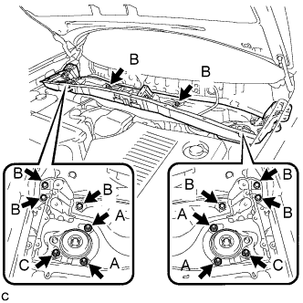
17. INSTALL OUTER COWL TOP PANEL SUB-ASSEMBLY


    C175030E01
  1. Install the outer cowl top panel sub-assembly with the 8 bolts and 6 nuts.

    Torque:
    Nut A:
    85 N*m{ 866 kgf*cm , 63 ft.*lbf }
    Bolt B:
    8.8 N*m{ 90 kgf*cm , 78 in.*lbf }
    Nut C:
    8.8 N*m{ 90 kgf*cm , 78 in.*lbf }


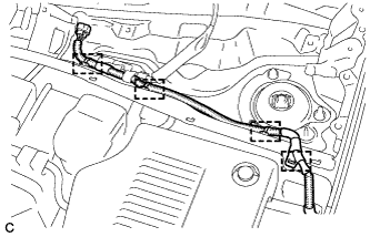
    C175029
  1. Engage the 4 clamps.


18. INSTALL WINDSHIELD WIPER MOTOR AND LINK ASSEMBLY


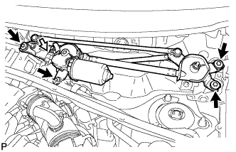
    E150150
  1. Install the windshield wiper motor and link assembly with the 4 bolts.

    Torque:
    7.0 N*m{ 71 kgf*cm , 62 in.*lbf }

  1. Connect the connector.


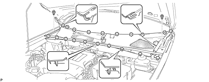
19. INSTALL COWL TOP VENTILATOR LOUVER SUB-ASSEMBLY


  1. Engage the 20 claws.


    E150149

  1. Install the cowl top ventilator louver sub-assembly with the 2 clips.


    E150146
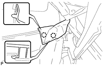
  1. Engage the 2 claws and connect the front fender to cowl side seal LH.


    E150147
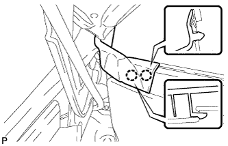
  1. Engage the 2 claws and connect the front fender to cowl side seal RH.


20. INSTALL HOOD TO COWL TOP SEAL


    E150148
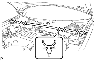
  1. Engage the 8 clips and install the hood to cowl top seal.


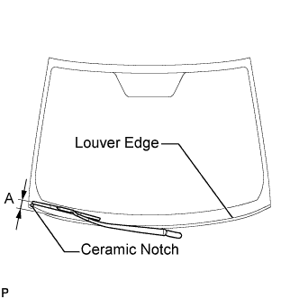
21. INSTALL FRONT WIPER ARM AND BLADE ASSEMBLY RH
  1. Operate the wiper and stop the windshield wiper motor at the automatic stop position.


  1. When reinstalling:


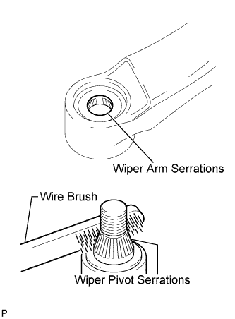
      E112237E01
    1. Clean the wiper arm serrations.

    2. Clean the wiper pivot serrations with a wire brush.


    E147125E01
  1. Install the front wiper arm and blade assembly RH with the nut to the position shown in the illustration.

    Torque:
    24 N*m{ 245 kgf*cm , 18 ft.*lbf }

    HINT:
    Hold the wiper arm by hand when tightening the nut.

    Area
    Measurement
    A
    25.6 mm (1.00 in.)


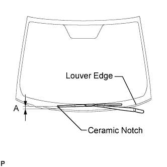
22. INSTALL FRONT WIPER ARM AND BLADE ASSEMBLY LH
  1. Operate the wiper and stop the windshield wiper motor at the automatic stop position.


  1. When reinstalling:


      E112237E01
    1. Clean the wiper arm serrations.

    2. Clean the wiper pivot serrations with a wire brush.


    E152618E01
  1. Install the front wiper arm and blade assembly LH with the nut to the position shown in the illustration.

    Torque:
    24 N*m{ 245 kgf*cm , 18 ft.*lbf }

    HINT:
    Hold the wiper arm by hand when tightening the nut.

    Area
    Measurement
    A
    31.9 mm (1.26 in.)

  1. Operate the front wipers while spraying washer fluid onto the windshield glass. Make sure that the front wipers function properly and the wipers do not come into contact with the vehicle body.


23. INSTALL SERVICE PLUG GRIP

NOTICE:
Before connecting the service plug, check that no parts and tools remain and that the high voltage terminals and connectors are connected securely.


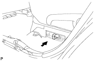
    A176049
  1. Wear insulated gloves, then insert the service plug.

  1. Push down on the grip to lock.


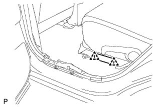
    A175635
  1. Close the reclining hinge cover.

    NOTICE:
    Check that the 2 clips are securely connected to the battery carrier bracket (click sound).


    A175634
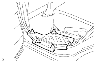
  1. Close the rear door scuff plate LH.

    NOTICE:
    Check that the 5 clips are securely connected to the battery carrier bracket (click sound).


24. CONNECT CABLE TO NEGATIVE BATTERY TERMINAL

NOTICE:
When disconnecting the cable, some systems need to be initialized after the cable is reconnected (Click here).


25. ADD COOLANT (for Inverter)

NOTICE:
  1. Do not reuse the drained coolant because it may contain foreign objects.
  2. If the vehicle is driven with air in the inverter cooling system, the following DTCs may be set.

    DTC Code
    Detection Item
    P0A01-725
    Motor Electronics Coolant Temperature Sensor Circuit Range / Performance
    P0A01-726
    Motor Electronics Coolant Temperature Sensor Circuit Range / Performance
    P0A78-284
    Drive Motor "A" Inverter Performance
    P0A7A-322
    Generator Inverter Performance
    P0A93-346
    Inverter Cooling System Performance
    P0A94-553
    DC / DC Converter Performance
    P0AEE-276
    Motor Inverter Temperature Sensor "A" Circuit Range / Performance
    P0AEE-277
    Motor Inverter Temperature Sensor "A" Circuit Range / Performance
    P3221-314
    Generator Inverter Temperature Sensor Circuit Range / Performance
    P3221-315
    Generator Inverter Temperature Sensor Circuit Range / Performance
    P3226-562
    DC/DC Boost Converter Temperature Sensor
    P3226-563
    DC/DC Boost Converter Temperature Sensor


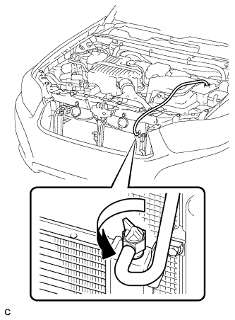
    A179308
  1. Loosen the bleeder plug shown in the illustration and connect a hose.

    NOTICE:
    Insert one end of the hose into the reserve tank.

  1. Add coolant to the reserve tank.


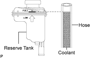
    C109303E01
  1. Add coolant until the level of coolant in the hose attached to the bleeder plug reaches the same level as the FULL line of the reserve tank.

    Coolant quantity:
    3.4 liter (3.6 US qts, 3.0 Imp. qts.)

  1. When using the Techstream:

    1. Connect the Techstream to the DLC3.

    2. Turn the power switch on (IG).

    3. On the Techstream, enter the following menus: Powertrain / Hybrid Control / Active Test / Activate the Water Pump.

    4. Keep the coolant at the FULL level in the reserve tank to compensate for the drop in coolant level when the air bleeds.

      Standard:
      Air bleeding from the coolant system is completed when the noise made by the water pump becomes smaller and the circulation of coolant in the reserve tank improves.

      HINT:
      Loud noise made by the water pump and poor circulation of coolant in the reserve tank indicates that there is air in the coolant system.

  1. When not using the Techstream:

    1. Turn the power switch on (READY). [*1]

    2. Turn the power switch off and add coolant to the FULL level because the coolant level drops as the air bleeds. [*2]

      NOTICE:
      1. Be sure to turn the power switch off before adding SLLC.
      2. Do not work on the components in the engine compartment while the vehicle is in the READY-on state because the engine is in intermittent operation.

    3. Repeat steps [*1] and [*2] until air bleeding from the coolant system is completed.

      Standard:
      Air bleeding from the coolant system is completed when the noise made by the water pump becomes smaller and the circulation of coolant in the reserve tank improves.

      HINT:
      Loud noise made by the water pump and poor circulation of coolant in the reserve tank indicates that there is air in the coolant system.

  1. When the air is completely bled from the coolant system, tighten the plug.


    C109304
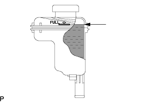
  1. Add coolant to the FULL mark of the reserve tank.


26. INSPECT FOR COOLANT LEAK (for Inverter)


27. INSTALL NO. 2 ENGINE ROOM SIDE COVER LH


    A173813
  1. Fit the clips and install the No. 2 engine room side cover LH.

    NOTICE:
    1. Be sure to engage the clips securely.
    2. Do not apply excessive force or do not hit the cover to engage the clips. This may cause the cover to break.


28. INSTALL COOL AIR INTAKE DUCT SEAL
  1. Install the cool air intake duct seal with the 11 clips.