 |
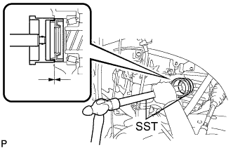
Install the oil seal on the LH side.
Using SST and a hammer, tap in a new oil seal until its surface is flush with the case edge.
- SST
- 09223-15020
09950-70010 (09951-07100)
Coat the lip of the oil seal with MP grease.
HYBRID TRANSAXLE OIL SEAL > INSTALLATION |
| 1. INSTALL HYBRID TRANSAXLE OIL SEAL |
|
Install the oil seal on the LH side.
Using SST and a hammer, tap in a new oil seal until its surface is flush with the case edge.
Coat the lip of the oil seal with MP grease.
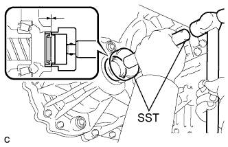 |
Install the oil seal on the RH side.
Using SST and a hammer, tap in a new oil seal until its surface is flush with the case edge.
Coat the lip of the oil seal with MP grease.
| 2. INSTALL FRONT NO. 3 EXHAUST PIPE SUB-ASSEMBLY |
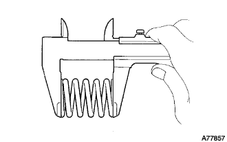 |
Using vernier calipers, measure the free length of the compression spring.
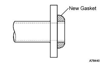 |
Install a new gasket to the front No. 3 exhaust pipe as shown in the illustration.
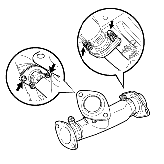 |
Install 2 new gaskets and the front No. 3 exhaust pipe with the 2 bolts and 2 new nuts.
Connect the heated oxygen sensor connector.
| 3. INSTALL FRONT EXHAUST PIPE ASSEMBLY |
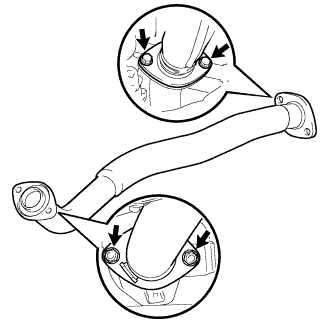 |
Install 2 new gaskets and the front No. 3 exhaust pipe with the 2 bolts and 2 new nuts.
Connect the heated oxygen sensor connector.
| 4. INSTALL FRONT DRIVE SHAFT ASSEMBLY LH |
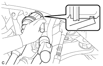 |
Align the shaft splines and install the drive shaft assembly LH with a brass bar and hammer.
| 5. INSTALL FRONT DRIVE SHAFT ASSEMBLY RH |
Install the front drive shaft assembly RH.
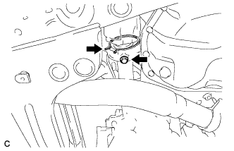 |
Install a new bearing bracket hole snap ring and bolt.
| 6. INSTALL FRONT SHOCK ABSORBER WITH COIL SPRING |
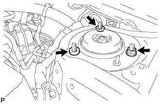 |
Install the front shock absorber with coil spring (upper side) with the nut and 2 spacers.
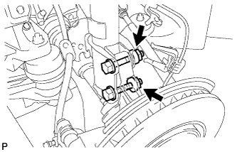 |
Install the front shock absorber with coil spring (lower side) to the steering knuckle and insert the 2 bolts and 2 nuts.
| 7. INSTALL FRONT STABILIZER LINK ASSEMBLY |
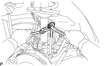 |
Install the front stabilizer link assembly to the front shock absorber with the nut.
| 8. INSTALL FRONT AXLE ASSEMBLY |
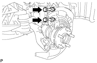 |
Install the front axle assembly to the front shock absorber with the 2 bolts and 2 nuts.
| 9. INSTALL FRONT DRIVE SHAFT ASSEMBLY |
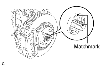 |
Align the matchmarks and install the front drive shaft assembly to the front axle hub sub-assembly.
| 10. CONNECT FRONT LOWER NO. 1 SUSPENSION ARM SUB-ASSEMBLY |
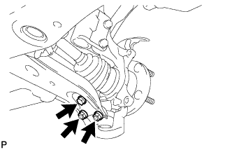 |
Install the front lower suspension arm to the front lower ball joint with the bolt and 2 nuts.
| 11. CONNECT TIE ROD ASSEMBLY |
Connect the tie rod assembly LH to the steering knuckle with the nut.
Install a new cotter pin.
| 12. INSTALL FRONT DISC |
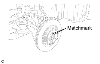 |
Align the matchmarks and install the front disc.
| 13. INSTALL FRONT DISC BRAKE CALIPER ASSEMBLY |
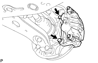 |
Install the front disc brake caliper assembly to the steering knuckle with the 2 bolts.
| 14. INSTALL FRONT AXLE SHAFT NUT |
Clean the threaded parts on the drive shaft and front axle shaft nut LH using a non-residue solvent.
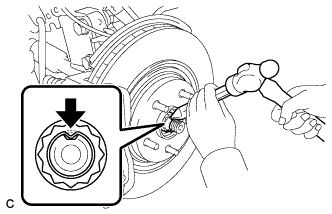 |
Using a socket wrench (30 mm), install a new front axle shaft nut.
Using a chisel and hammer, stake the front axle shaft nut.
| 15. INSTALL FRONT SPEED SENSOR |
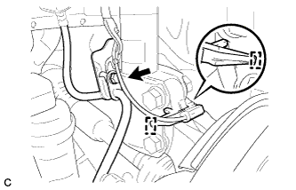 |
Install the front speed sensor and front flexible hose with the bolt.
Install the clamp.
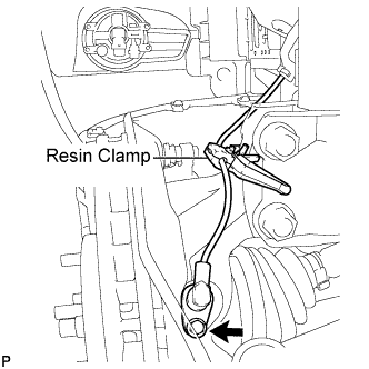 |
Install the resin clamp and front speed sensor with the bolt.
| 16. INSTALL OUTER COWL TOP PANEL SUB-ASSEMBLY |
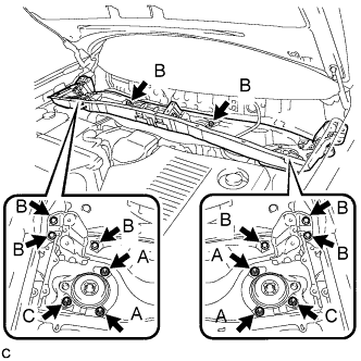 |
Install the outer cowl top panel sub-assembly with the 8 bolts and 6 nuts.
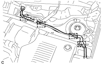 |
Engage the 4 clamps.
| 17. FULLY TIGHTEN FRONT SUPPORT TO FRONT SHOCK ABSORBER NUT |
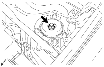 |
Fully tighten the front support to front shock absorber nut.
| 18. INSTALL WINDSHIELD WIPER MOTOR AND LINK ASSEMBLY |
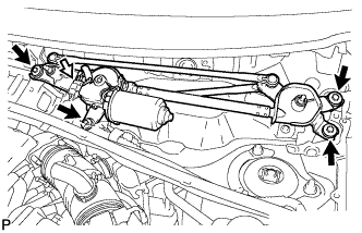 |
Install the windshield wiper motor and link assembly with the 4 bolts.
Connect the connector.
| 19. INSTALL COWL TOP VENTILATOR LOUVER SUB-ASSEMBLY |
Engage the 20 claws.
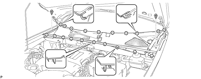
Install the cowl top ventilator louver sub-assembly with the 2 clips.
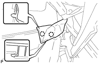 |
Engage the 2 claws and connect the front fender to cowl side seal LH.
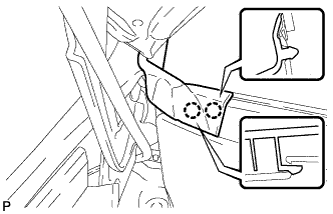 |
Engage the 2 claws and connect the front fender to cowl side seal RH.
| 20. INSTALL FRONT WIPER ARM AND BLADE ASSEMBLY RH |
Operate the wiper and stop the windshield wiper motor at the automatic stop position.
When reinstalling:
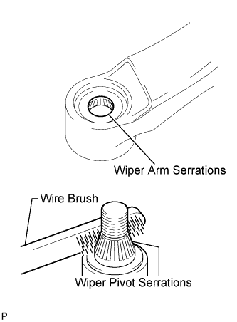 |
Clean the wiper arm serrations.
Clean the wiper pivot serrations with a wire brush.
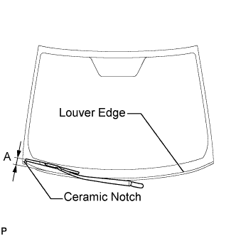 |
Install the front wiper arm and blade assembly RH with the nut to the position shown in the illustration.
| Area | Measurement |
| A | 25.6 mm (1.00 in.) |
| 21. INSTALL FRONT WIPER ARM AND BLADE ASSEMBLY LH |
Operate the wiper and stop the windshield wiper motor at the automatic stop position.
When reinstalling:
|
Clean the wiper arm serrations.
Clean the wiper pivot serrations with a wire brush.
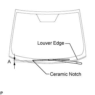 |
Install the front wiper arm and blade assembly LH with the nut to the position shown in the illustration.
| Area | Measurement |
| A | 31.9 mm (1.26 in.) |
Operate the front wipers while spraying washer fluid onto the windshield glass. Make sure that the front wipers function properly and the wipers do not come into contact with the vehicle body.
| 22. ADD AND INSPECT HYBRID TRANSAXLE FLUID |
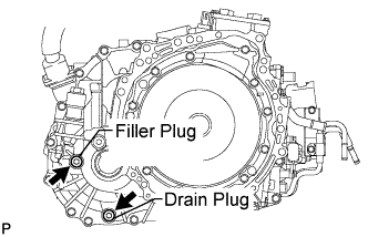 |
Using a socket hexagon wrench 10 mm, remove the filler plug and gasket.
Using a socket hexagon wrench 10 mm, remove the drain plug and gasket.
Using a socket hexagon wrench 10 mm, install the drain plug, and a new gasket.
| 23. INSTALL FRONT WHEELS |
| 24. INSPECT AND ADJUST FRONT WHEEL ALIGNMENT |
| 25. INSTALL NO. 2 ENGINE UNDER COVER |
Install the 2 bolts and No. 2 engine under cover.
| 26. INSTALL NO. 1 ENGINE UNDER COVER |
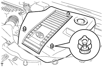 |
Fit the clips and install the No. 2 engine room side cover LH.
| 27. CHECK ABS SPEED SENSOR SIGNAL |