Home › RESTRAINTS › SUPPLEMENTAL RESTRAINT SYSTEM › CENTER AIRBAG SENSOR ASSEMBLY

CENTER AIRBAG SENSOR ASSEMBLY > INSTALLATION

for Preparation Click here


1. INSTALL CENTER AIRBAG SENSOR ASSEMBLY
  1. Check that the power switch is off.

  1. Check that the battery negative (-) cable is disconnected.

    CAUTION:
    Wait for at least 90 seconds after disconnecting the cable to prevent airbag deployment.


    C165111E01
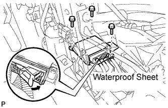
  1. Install the center airbag sensor assembly with the 3 bolts.

    Torque:
    18 N*m{ 184 kgf*cm , 13 ft.*lbf }

    NOTICE:
    1. If the center airbag sensor assembly has been dropped, or there are any cracks, dents or other defects in the case, bracket or connector, replace it with a new one.
    2. When installing the center airbag sensor assembly, be careful that the SRS wiring does not interfere with other parts and that it is not pinched between other parts.
    3. When the power switch is first turned on (READY) after the center airbag sensor assembly has been replaced, make sure that no one is in the vehicle.
  1. Check that there are no loose parts after installing the center airbag sensor assembly.

  1. Connect the holder (with connectors).

    NOTICE:
    When handling the airbag connector, take care not to damage the airbag wire harness.

  1. Check that the waterproof sheet is properly set.


2. INSTALL FRONT NO. 2 CONSOLE BOX INSERT


    B168374
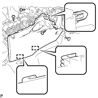
  1. Engage the claw and 2 guides.

  1. Install the front No. 2 console box insert with the 3 screws <E> and clip.


3. INSTALL FRONT NO. 1 CONSOLE BOX INSERT


    B168373
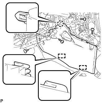
  1. Engage the claw and 2 guides.

  1. Install the front No. 1 console box insert with the 3 screws <E> and 2 clips.


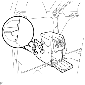
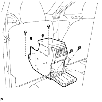
4. INSTALL CONSOLE BOX ASSEMBLY (w/o Rear Air Conditioning System)


    B173629
  1. Engage the 6 claws.


    B173628
  1. Install the console box assembly with the 4 bolts and 2 screws.


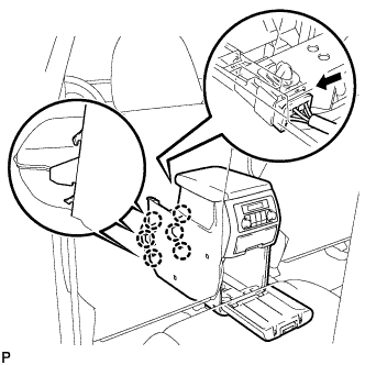
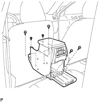
5. INSTALL CONSOLE BOX ASSEMBLY (w/ Rear Air Conditioning System)


    B175149
  1. Engage the 6 claws.

  1. Connect the connector.


    B181135
  1. Install the console box assembly with the 4 bolts and 2 screws.


6. INSTALL LOWER REAR CONSOLE BOX
  1. Install the lower rear console box.


7. INSTALL NO. 2 CONSOLE BOX DUCT (w/o Rear Air Conditioning System)


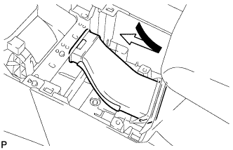
    B173013
  1. Install the No. 2 console box duct as shown in the illustration.


8. INSTALL UPPER CONSOLE PANEL SUB-ASSEMBLY


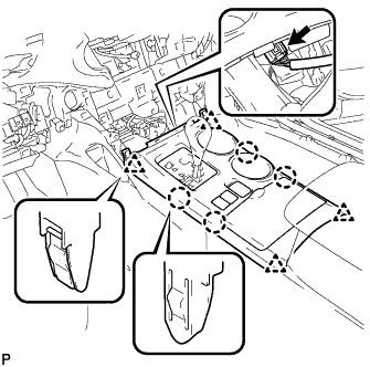
    B168372
  1. Connect the connector.

  1. Engage the 4 claws and 4 clips, and install the upper console panel sub-assembly.


9. INSTALL LOWER INSTRUMENT PANEL SUB-ASSEMBLY
  1. Connect each connector and clamp.


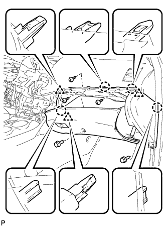
    B168370
  1. Engage the 4 claws and 3 clips.

  1. Install the lower instrument panel sub-assembly with the 2 bolts <B> and 3 screws <E>.


10. INSTALL NO. 2 INSTRUMENT PANEL UNDER COVER SUB-ASSEMBLY


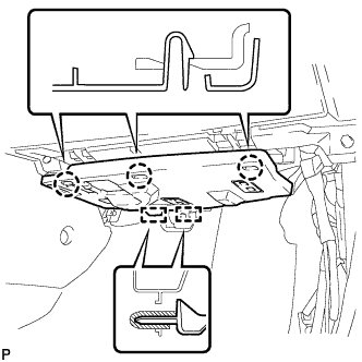
    B173000
  1. Engage the 2 guides.

  1. Engage the 3 claws and install the No. 2 instrument panel under cover sub-assembly.


11. INSTALL COWL SIDE TRIM SUB-ASSEMBLY RH

HINT:
Use the same procedure for the RH side and the LH side .


12. INSTALL FRONT DOOR SCUFF PLATE RH

HINT:
Use the same procedure for the RH side and the LH side .


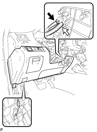
13. INSTALL LOWER INSTRUMENT PANEL FINISH PANEL SUB-ASSEMBLY


    B173009
  1. Connect the hood lock control cable assembly.

  1. Connect each connector and the aspirator duct.


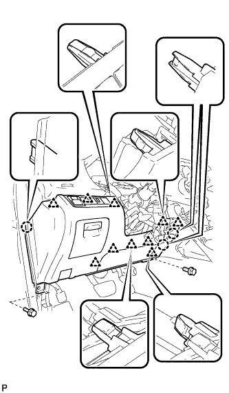
    B173021
  1. Engage the 3 claws and 10 clips.

  1. Install the lower instrument panel finish panel sub-assembly with the 2 bolts <B>.


14. INSTALL COWL SIDE TRIM SUB-ASSEMBLY LH


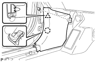
    B173227
  1. Engage the claw and clip, install the cowl side trim sub-assembly LH.

  1. Install the clip.


15. INSTALL FRONT DOOR SCUFF PLATE LH


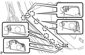
    B173224
  1. Engage the guide and the 8 claws, and install the front door scuff plate LH.


16. INSTALL CENTER INSTRUMENT CLUSTER FINISH PANEL ASSEMBLY


    B184681E01
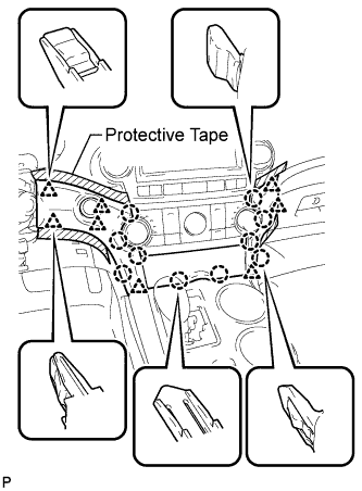
  1. Apply protective tape to the areas shown in the illustration.

  1. Connect each connector.

  1. Engage the 10 claws and 8 clips, and install the center instrument cluster finish panel assembly.

    NOTICE:
    Do not the damage the instrument panel safety pad assembly and lower instrument panel finish panel sub-assembly.


17. CONNECT CABLE TO NEGATIVE BATTERY TERMINAL

NOTICE:
When disconnecting the cable, some systems need to be initialized after the cable is reconnected (Click here).


18. INSPECT SRS WARNING LIGHT
  1. Inspect the SRS warning light (Click here).