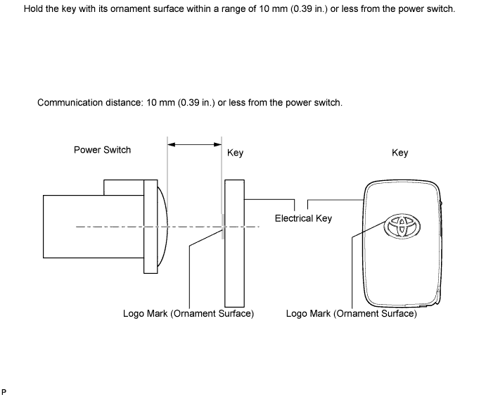
Vehicles with the smart key system do not have a key slot. Therefore, hold the key close to the power switch to register the key, as shown in the illustration below.
REPAIR INSTRUCTION > INITIALIZATION |
| PROCEDURES NECESSARY WHEN BATTERY TERMINAL IS DISCONNECTED/RECONNECTED |
| Necessary Procedure | Procedure Detail | Effect / Inoperative Functions When Necessary Procedures are not Performed | Note |
| Idle speed control learning | Perform initialization (Click here) | - | Perform the initialization using Techstream. |
| Reset back door close position | Fully close the back door to turn off the courtesy switch. | Power back door function | If the back door is closed when disconnecting the cable from the battery terminal, it is not necessary to reset it. |
| PROCEDURES NECESSARY WHEN ECU OR OTHER PARTS ARE REPLACED |
| Replacement Part | Necessary Procedure | Effect / Inoperative Function when Necessary Procedures are not Performed | Note |
| Hybrid vehicle control ECU | ECU communication ID registration | Starting of hybrid system | - |
| Vehicle Identification Number (VIN) registration | MIL comes on | Use the Techstream. | |
| Idle speed control learning (Perform initialization) | - | Use the Techstream. | |
| Tire pressure warning ECU | Register transmitter IDs |
| - |
| Tire pressure warning valve and transmitter | Register transmitter IDs |
| Even if only one transmitter is replaced, IDs for all 4 or 5 wheels must be registered. |
| Skid control ECU |
|
| Perform yaw rate and acceleration sensor zero point calibration with the power switch on (IG). |
| Brake actuator assembly |
| Brakes do not operate properly | - |
|
|
| - |
| Yaw rate and acceleration sensor |
|
| Perform yaw rate and acceleration sensor zero point calibration with the power switch on (IG). |
| Front wheel alignment adjustment |
| VSC does not operate properly | Perform yaw rate and acceleration sensor zero point calibration with the power switch on (IG). |
| Steering lock actuator (Steering lock ECU) | ECU code registration | Starting of hybrid system | - |
|
|
| - |
| Key ID registration |
| - |
| ID code box |
|
| - |
| Perform power window reset (initialization of pulse sensor) |
| Necessary when removed and installed. |
| Back door lock motor | Reset back door close position | Power back door function | - |
| Perform sliding roof drive gear reset |
| Necessary when removed and installed (Not necessary when the sliding roof drive gear (sliding roof ECU) is removed and installed together with the sliding roof housing). |
| DESCRIPTION OF CODE REGISTRATION (Engine Immobiliser System) |
Vehicles with the smart key system do not have a key slot. Therefore, hold the key close to the power switch to register the key, as shown in the illustration below.
| PART REPLACEMENT AND KEY REGISTRATION (Engine Immobiliser System) |
The following table shows ECU replacement and key registration procedures for cases in which a malfunctioning ECU has been identified through the troubleshooting of the smart key system.
| Part to be replaced | Condition | Procedure | Reference | |
| Certification ECU (Smart key ECU assembly) | Customer has brought all keys | 1. Replace certification ECU (smart key ECU assembly) | - | |
| 2. Reregister all keys (New key ID registration) | PROCEDURE "B" | |||
| Some keys are lost | Key ID codes can be registered and erased | 1. Erase key codes (Key ID erasure) | PROCEDURE "D" | |
| 2. Perform additional key registration procedure (Additional key ID registration) | PROCEDURE "C" | |||
| 3. Replace certification ECU (smart key ECU assembly) | - | |||
4. Reregister all keys (New key ID registration)
| PROCEDURE "B" | |||
| Key ID codes cannot be either registered or erased | 1. Replace certification ECU (smart key ECU assembly) | - | ||
| 2. Replace ID code box (immobiliser code ECU) | - | |||
3. Reregister all keys (New key ID registration)
| PROCEDURE "A" | |||
| 4. ECU communication ID registration | PROCEDURE "G" | |||
| Certification ECU (Smart key ECU assembly) | All keys are lost | 1. Replace certification ECU (smart key ECU assembly) | - | |
| 2. Replace ID code box (immobiliser code ECU) | - | |||
3. Reregister all keys (New key ID registration)
| PROCEDURE "A" | |||
| 4. ECU communication ID registration | PROCEDURE "G" | |||
| ID code box (Immobiliser code ECU) | Customer has brought at least 1 key | 1. Replace ID code box (immobiliser code ECU) | - | |
| 2. Register recognition codes in ECUs (ECU code registration) | PROCEDURE "F" | |||
| 3. ECU communication ID registration | PROCEDURE "G" | |||
| All keys are lost | 1. Replace ID code box (immobiliser code ECU) | - | ||
| 2. Replace certification ECU (smart key ECU assembly) | - | |||
3. Reregister all keys (New key ID registration)
| PROCEDURE "A" | |||
| 4. ECU communication ID registration | PROCEDURE "G" | |||
| Steering lock ECU | Customer has brought at least 1 key | 1. Replace steering lock ECU | - | |
| 2. Register recognition codes in ECUs (ECU code registration) | PROCEDURE "F" | |||
| All keys are lost | 1. Replace steering lock ECU | - | ||
| 2. Replace certification ECU (smart key ECU assembly) | - | |||
| 3. Replace ID code box (immobiliser code ECU) | - | |||
4. Reregister all keys (New key ID registration)
| PROCEDURE "A" | |||
| 5. ECU communication ID registration | PROCEDURE "G" | |||
| Main body ECU (Instrument panel junction block) | No condition required | Replace main body ECU (instrument panel junction block) | - | |
| Hybrid vehicle control ECU | No condition required | 1. Replace hybrid vehicle control ECU | - | |
| 2. ECU communication ID registration | PROCEDURE "G" | |||
| Key (for replacement) | Customer has brought at least 1 key | 1. Using remaining key(s), erase lost key code (Key ID erasure) | PROCEDURE "D" | |
| 2. Register additional keys as necessary (Additional key ID registration) | PROCEDURE "C" | |||
| All keys are lost | 1. Erase all key codes (All key ID erasure) | PROCEDURE "E" | ||
2. Register all keys (New key ID registration)
| PROCEDURE "A" | |||
| Key (for addition) | Customer has brought at least 1 key
| 1. Register additional key(s) as necessary (Additional key ID registration) | PROCEDURE "C" | |
| KEY REGISTRATION (Engine Immobiliser System) |
PROCEDURE "A"
New key ID registration (when replacing the certification ECU (smart key ECU assembly) and ID code box (immobiliser code ECU), or when replacing the certification ECU (smart key ECU assembly), ID code box (immobiliser code ECU) and steering lock ECU)
| Process | Procedure |
| 1. Start of registration |
|
| 2. Confirmation of ECU code |
|
| 3. Verification of unregistered key*1
|
|
| 4. Registration of ID code |
|
| 5. End of registration |
|
PROCEDURE "B"
New key ID registration (when replacing the certification ECU (smart key ECU assembly))
| Process | Procedure |
| 1. Start of registration |
|
| 2. Confirmation of ECU code |
|
| 3. Confirmation of all registered keys*1
|
|
| 4. Confirmation of ECU code |
|
| 5. Verification of unregistered key*2
|
|
| 5. Registration of ID code |
|
| 6. End of registration |
|
PROCEDURE "C"
Additional key ID registration
| Process | Procedure |
| 1. Start of registration |
|
| 2. Confirmation of registered key*1
|
|
| 3. Confirmation of ECU code |
|
| 4. Verification of unregistered key*2
|
|
| 5. Registration of ID code |
|
| 6. End of registration |
|
PROCEDURE "D"
Key ID erasure
| Process | Procedure |
| 1. Start of erasure |
|
2. Confirmation of registered key*1
|
|
| 3. Confirmation of ECU code |
|
| 4. Erasure of ID code |
|
| 5. End of erasure |
|
PROCEDURE "E"
All key ID erasure
| Process | Procedure |
| 1. Start of erasure |
|
| 3. Confirmation of ECU code |
|
| 4. Erasure of ID code |
|
| 5. End of erasure |
|
PROCEDURE "F"
ECU code registration
| Process | Procedure |
| 1. Start of registration |
|
| 2. Confirmation of registered key*1
|
|
| 3. Registration of ECU code |
|
| 4. End of registration |
|
PROCEDURE "G"
ECU communication ID registration
Using SST, connect terminals TC and CG of the DLC3.
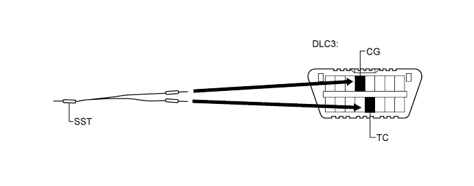
Turn the power switch on (IG) and leave it as is for 30 minutes.
Turn the power switch off and disconnect terminals TC and CG.
Check that the hybrid system starts and stays on for more than 3 seconds.
| VEHICLE IDENTIFICATION NUMBER (VIN) REGISTRATION |
Description
Read VIN: This process allows the VIN stored in the hybrid vehicle control ECU to be read, in order to confirm that the two VINs, provided with the vehicle and stored in the hybrid vehicle control ECU, are the same.
Write VIN: This process allows the VIN to be input into the hybrid vehicle control ECU. If the hybrid vehicle control ECU is changed, or the hybrid vehicle control ECU VIN and the vehicle VIN do not match, the VIN can be registered, or overwritten in the hybrid vehicle control ECU by following this procedure.
Read VIN
Confirm the vehicle VIN.
Connect the Techstream to the DLC3.
Turn the power switch on (IG).
Turn the Techstream on.
Enter the following menus: Powertrain / Hybrid Control / Utility / VIN / VIN Read.
Write VIN
Confirm the vehicle VIN.
Connect the Techstream to the DLC3.
Turn the power switch on (IG).
Turn the Techstream on.
Enter the following menus: Powertrain / Hybrid Control / Utility / VIN / VIN Write.
| IDLE SPEED CONTROL LEARNING (PERFORM INITIALIZATION) (SFI System) |
Apply the parking brake and chock the wheels.
Connect the Techstream to the DLC3.
Put the engine in the inspection mode (Click here).
Select the following menu items: Powertrain / Engine and ECT / Data List / Coolant Temp.
Warm up the engine with the A/C switch off until the coolant temperature becomes 83°C (181°F) or more.
Select the following menu items: Powertrain / Hybrid Control / Data List / State of Charge.
Move the shift lever to the N position, set the A/C switch to MAX cool or turn on the front defroster, and leave the vehicle until the SOC value is below 40%.
Move the shift lever to the P position and turn the power switch off.
Disconnect the negative terminal from the auxiliary battery and leave it for 1 minute or more.
Reconnect the negative terminal to the auxiliary battery and turn the power switch on (IG).
Select the following menu items: Powertrain / Engine and ECT / Data List / Coolant Temp.
Check that the engine coolant temperature is 83°C (181°F) or more.
Select the following menu items: Powertrain / Engine and ECT / Data List / Calculate Load.
Move the shift lever to the D position while depressing the brake pedal with your left foot.
Depress the accelerator pedal with your right foot while firmly depressing the brake pedal with your left foot, and maintain an engine load value of 45% or more (accelerator pedal depressed 60 to 70%) for approximately 30 seconds.
Shift the shift lever to the P position. Turn the power switch off and then wait for 5 seconds before turning the power switch on (READY).
Select the following menu items: Powertrain / Engine and ECT / Data List / ISC Learning.
Check that the air conditioner is off. Lightly depress the accelerator pedal and release it when the engine starts.
Check that "Complete" is displayed on Techstream screen.
| DESCRIPTION OF CODE REGISTRATION (Tire Pressure Warning System) |
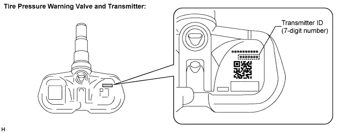
Before registration
When replacing the tire pressure warning ECU:
When replacing a tire pressure warning valve and transmitter:
| REGISTER TRANSMITTER ID (USING TECHSTREAM) (Tire Pressure Warning System) |
Set the air pressure of all tires to the specified value (Click here).
Turn the power switch off.
Connect the Techstream to the DLC3.
Turn the power switch on (IG) and turn the Techstream on.
Enter the menu items in this order: Chassis / Tire Pressure Monitor / Utility / ID Registration.
Perform the following procedures displayed on the screen.
Confirmation of transmitter ID registration.
Enter the menu items in this order: Chassis / Tire Pressure Monitor / Data List.
Read the "ID Tire Inflation Pressure" values.
Confirm that the data of tire pressure of all tires are displayed on the screen.
| PERFORM INITIALIZATION AND CALIBRATION OF LINEAR SOLENOID VALVE (When Using Techstream) (Electronically Controlled Brake System) |
Clear the stored linear solenoid valve calibration data.
Turn the power switch off.
Check that the steering wheel is in the straight-ahead position.
Check that the shift lever is in P.
Connect the Techstream to the DLC3.
Turn the power switch on (IG).
Turn the Techstream on.
Select the skid control ECU to clear the linear solenoid valve calibration data using the Techstream. Enter the following menus: Chassis / ABS/VSC/TRAC / Utility / Reset Memory.
Perform initialization and calibration of the linear solenoid valve.
Perform the zero point calibration of yaw rate and acceleration sensor (Click here).
Perform initialization and calibration of the linear solenoid valve.
Turn the power switch off.
Check that the steering wheel is in the straight-ahead position.
Check that the shift lever is in P.
Connect the Techstream to the DLC3.
Turn the power switch on (IG) with the brake pedal released.
Turn the Techstream on.
Switch the skid control ECU to the Test Mode using the Techstream. Enter the following menus: Chassis / ABS/VSC/TRAC / Utility / ECB* Utility / Linear Valve Offset.
*: Electronically Controlled Brake System
Leave the vehicle stationary without depressing the brake pedal for 1 or 2 minutes.
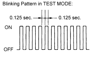 |
Check that the interval between blinks of the brake warning light / yellow (minor malfunction) changes from 1 second to 0.25 seconds.
Check that DTC C1345 (linear solenoid valve offset learning undone) which indicates trouble with stroke sensor zero point learning is not output when the brake warning light / yellow (minor malfunction) changes to the Test Mode display upon initialization and calibration of the linear solenoid valve completion.
Enter the normal mode from the Test Mode following the Techstream directions.
| PERFORM INITIALIZATION AND CALIBRATION OF LINEAR SOLENOID VALVE (When not Using Techstream) (Electronically Controlled Brake System) |
Clear the stored linear solenoid valve calibration data.
Turn the power switch off.
Check that the steering wheel is in the straight-ahead position.
Check that the shift lever is in P.
Turn the power switch on (IG) with the brake pedal released.
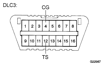 |
Using SST, connect and disconnect terminals TS and CG of the DLC3 4 times or more within 8 seconds.
Check that no codes other than ABS code 42, VSC code 45 and electronically controlled brake system code 48, 66, or 95 are stored in the diagnostic system.
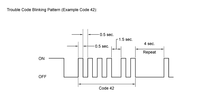
Remove SST from the terminals of the DLC3.
Perform initialization and calibration of the linear solenoid valve.
Perform the zero point calibration of yaw rate and acceleration sensor (Click here).
Perform initialization and calibration of the linear solenoid valve.
Turn the power switch off.
Check that the steering wheel is in the straight-ahead position.
Check that the shift lever is in P.
|
Using SST, connect terminals TS and CG of the DLC3.
Turn the power switch on (IG) with the brake pedal released.
Leave the vehicle stationary without depressing the brake pedal for 1 or 2 minutes.
|
Check that the interval between blinks of the brake warning light / yellow (minor malfunction) changes from 1 second to 0.25 seconds.
Check that DTC 66 (linear solenoid valve offset learning undone) which indicates trouble with stroke sensor zero point learning is not output when the brake warning light / yellow (minor malfunction) changes to the Test Mode display upon initialization and calibration of the linear solenoid valve completion.
Turn the power switch off and disconnect the SST from the DLC3.
| OBTAIN ZERO POINT OF YAW RATE AND ACCELERATION SENSOR (When Using Techstream) (Electronically Controlled Brake System) |
Clear the zero point calibration data.
Turn the power switch off.
Check that the steering wheel is in the straight-ahead position.
Check that the shift lever is in P.
Connect the Techstream to the DLC3.
Turn the power switch on (IG).
Turn the Techstream on.
Select the skid control ECU to clear the zero point calibration data using the Techstream. Enter the following menus: Chassis / ABS/VSC/TRAC / Utility / Reset Memory.
Turn the power switch off.
Perform the zero point calibration of the yaw rate and acceleration sensor.
Turn the power switch off.
Check that the steering wheel is in the straight-ahead position.
Check that the shift lever is in P.
Connect the Techstream to the DLC3.
Turn the power switch on (IG).
Turn the Techstream on.
Switch the skid control ECU to Test Mode using the Techstream. Enter the following menus: Chassis / ABS/VSC/TRAC / Utility / Test Mode.
After Test Mode has been entered, keep the vehicle stationary on a level surface for 2 seconds or more.
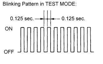 |
Check that the ABS warning, brake warning / yellow (minor malfunction) and slip indicator lights come on for several seconds and then blink in Test Mode.
Turn the power switch off and disconnect the Techstream.
| OBTAIN ZERO POINT OF YAW RATE AND ACCELERATION SENSOR (When not Using Techstream) (Electronically Controlled Brake System) |
Clear the zero point calibration data.
Turn the power switch off.
Check that the steering wheel is in the straight-ahead position.
Check that the shift lever is in P.
Turn the power switch on (IG).
The warning light and indicator light come on for 3 seconds to indicate that the initial check is completed.
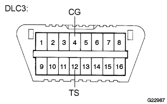 |
Using SST, connect and disconnect terminals TS and CG of the DLC3 4 times or more within 8 seconds.
Check that no codes other than ABS code 42, VSC code 45 and electronically controlled brake system code 48, 66, or 95 are stored in the diagnostic system.
Perform the zero point calibration of the yaw rate and acceleration sensor.
Turn the power switch off.
Check that the steering wheel is in the straight-ahead position.
Check that the shift lever is in P.
|
Using SST, connect terminals TS and CG of the DLC3.
Turn the power switch on (IG).
After Test Mode has been entered, keep the vehicle stationary on a level surface for 2 seconds or more.
|
Check that the ABS warning, brake warning / yellow (minor malfunction) and slip indicator lights come on for several seconds and then blinks in Test Mode.
Turn the power switch off and disconnect SST from the DLC3.
| ZERO POINT CALIBRATION (Occupant Classification System) |
Zero point calibration procedures
Check that all of the following conditions are met:
Adjust the seat position according to the table below.
| Adjustment Item | Position |
| Slide Direction | Rearmost position |
| Reclining Angle | Upright position |
| Headrest Height | Lowest position |
| Lifter Height | Lowest position |
Turn the power switch off.
Connect the Techstream to the DLC3.
Turn the power switch on (IG) and turn the Techstream on.
Enter the following menus: Body Electrical / Occupant Detection / Utility / Zero Point Calibration.
Perform the zero point calibration by following the prompts on the Techstream screen.
| SENSITIVITY CHECK (Occupant Classification System) |
Sensitivity check procedures
Turn the power switch off.
Connect the Techstream to the DLC3.
Turn the power switch on (IG) and turn the Techstream on.
Enter the following menus: Body Electrical / Occupant Detection / Utility / Sensitivity Check.
Perform the sensitivity check by following the prompts on the Techstream screen.
Confirm that the initial sensor reading is within the specified range.
Place a 30 kg (66.14 lb) weight (eg. a 30 kg (66.14 lb) of lead mass) onto the front passenger seat.
Confirm that the sensitivity is within the specified range.
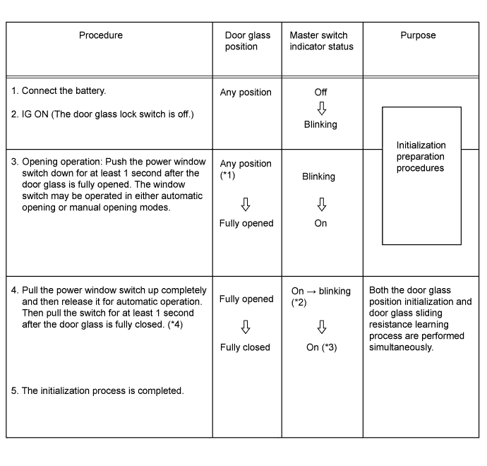
| INITIALIZE POWER WINDOW CONTROL SYSTEM (POWER WINDOW REGULATOR MOTOR ASSEMBLY (ON DRIVER SIDE)) (Power Window Control System) |
Inspection procedure
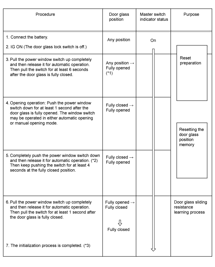
| TO RETURN THE SYSTEM TO THE PRE-INITIALIZED CONDITION (Power Window Control System) |
Procedure
| RESET BACK DOOR CLOSE POSITION (Power Back Door System) |
When disconnecting the cable from the battery terminal, fully close the back door to turn off the courtesy switch.
| INITIALIZE SLIDING ROOF DRIVE GEAR SUB-ASSEMBLY (Sliding Roof System) |
Initialization
| Sliding Roof Condition | Proceed to |
| The sliding roof AUTO function does not operate. | [A] |
| The sliding roof AUTO function | [B] |
| Although the sliding roof AUTO function operates, the roof glass stops moving or starts moving in the opposite direction while tilting downward. | [B] |
| Although the sliding roof AUTO function operates, the roof glass stops moving or starts moving in the opposite direction while sliding closed. | [C] |
[A] The sliding roof AUTO function does not operate.
[B] Although the sliding roof AUTO function operates, the roof glass stops moving or starts moving in the opposite direction while tilting downward.
[C] Although the sliding roof AUTO function operates, the roof glass stops moving or starts moving in the opposite direction while sliding closed.