 |
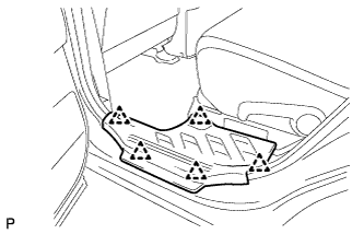
Remove the 5 clips and door scuff plate LH.
BRAKE CONTROL POWER SUPPLY > REMOVAL |
| 1. DISCONNECT CABLE FROM NEGATIVE BATTERY TERMINAL |
| 2. REMOVE SERVICE PLUG GRIP |
|
Remove the 5 clips and door scuff plate LH.
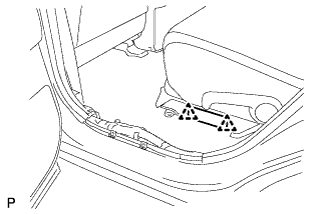 |
Remove the 2 clips and reclining hinge cover.
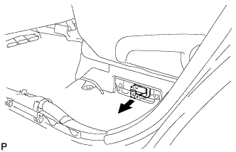 |
Wear insulated glove and remove the service plug grip, after sliding up the lever of the service plug grip.
| 3. REMOVE DECK BOARD ASSEMBLY |
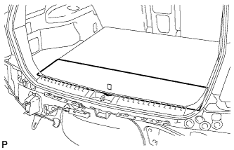 |
Remove the deck board assembly.
| 4. REMOVE NO. 3 DECK BOARD SUB-ASSEMBLY |
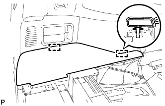 |
Disengage the 2 guides and remove the No. 3 deck board sub-assembly.
| 5. REMOVE NO. 2 DECK BOARD SUB-ASSEMBLY |
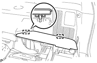 |
Disengage the 2 guides and remove the No. 2 deck board sub-assembly.
| 6. REMOVE TONNEAU COVER ASSEMBLY (w/ Tonneau Cover) |
Remove the tonneau cover assembly.
| 7. REMOVE REAR NO. 1 FLOOR BOARD (w/o Rear No. 2 Seat) |
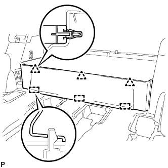 |
Disengage the 3 clips and the 3 guides, and remove the rear No. 1 floor board.
| 8. REMOVE REAR SEAT SIDE COVER LH (w/ Rear No. 2 Seat) |
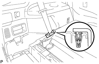 |
Disengage the 2 clips and remove the rear seat side cover LH.
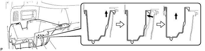
| 9. REMOVE DECK SIDE TRIM BOX LH |
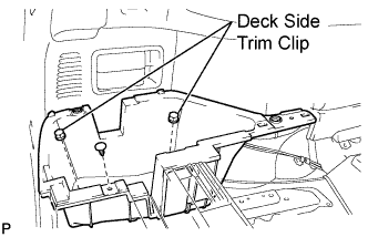 |
Remove the 2 deck side trim clips and clip.
Remove the deck side trim box LH as shown in the illustration.
| 10. REMOVE REAR SEAT SIDE COVER RH (w/ Rear No. 2 Seat) |
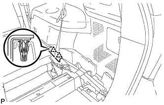 |
Disengage the 2 clips and remove the rear seat side cover RH.
| 11. REMOVE JACK CARRIER SUPPORT |
| 12. REMOVE JACK CARRIER CUSHION |
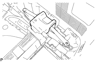 |
Remove the jack carrier cushion.
| 13. REMOVE JACK ASSEMBLY |
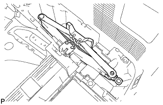 |
Remove the jack assembly.
| 14. REMOVE JACK CARRIER ASSEMBLY |
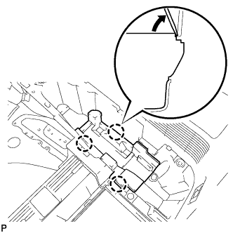 |
Using a screwdriver, disengage the 3 claws and remove the jack carrier assembly.
| 15. REMOVE DECK SIDE TRIM BOX RH |
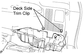 |
Remove the 2 deck side trim clips and clip.
Remove the deck side trim box RH as shown in the illustration.
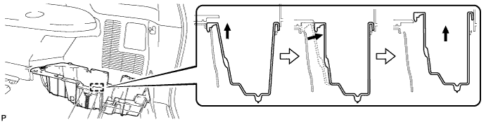
| 16. REMOVE DECK FLOOR BOARD ASSEMBLY (w/o Rear No. 2 Seat) |
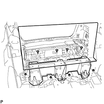 |
Remove the 4 bolts and 4 nuts.
Remove the deck floor board assembly.
| 17. REMOVE REAR MAT |
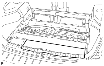 |
Remove the rear mat.
| 18. REMOVE DECK FLOOR BOARD ASSEMBLY (w/ Rear No. 2 Seat) |
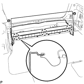 |
Disengage the 3 claws.
Remove the 2 nuts and the deck floor board assembly.
| 19. REMOVE REAR DECK FLOOR BOX (w/o Rear No. 2 Seat) |
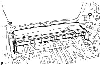 |
Remove the 2 nuts and the deck floor box.
| 20. REMOVE BRAKE CONTROL POWER SUPPLY WITH BRACKET |
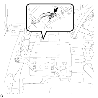 |
Disconnect the connector.
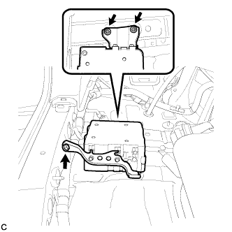 |
Remove the bolt, 2 nuts and the brake control power supply with bracket.
| 21. REMOVE BRAKE CONTROL POWER SUPPLY |
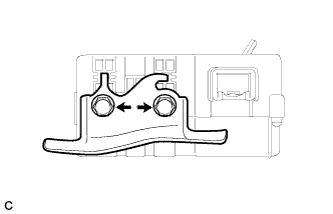 |
Remove the 2 bolts and No. 1 brake control power supply bracket.
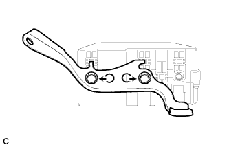 |
Remove the 2 bolts and No. 2 brake control power supply bracket.