 |
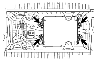
Install the battery smart unit with the 4 bolts.
- Torque:
- 7.5 N*m{ 76 kgf*cm , 66 in.*lbf }
BATTERY SMART UNIT > INSTALLATION |
| 1. INSTALL BATTERY SMART UNIT |
|
Install the battery smart unit with the 4 bolts.
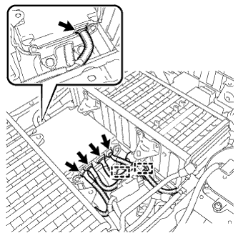 |
Connect the 5 connectors and 2 clamps.
| 2. CHECK HIGH VOLTAGE CABLE CONNECTION |
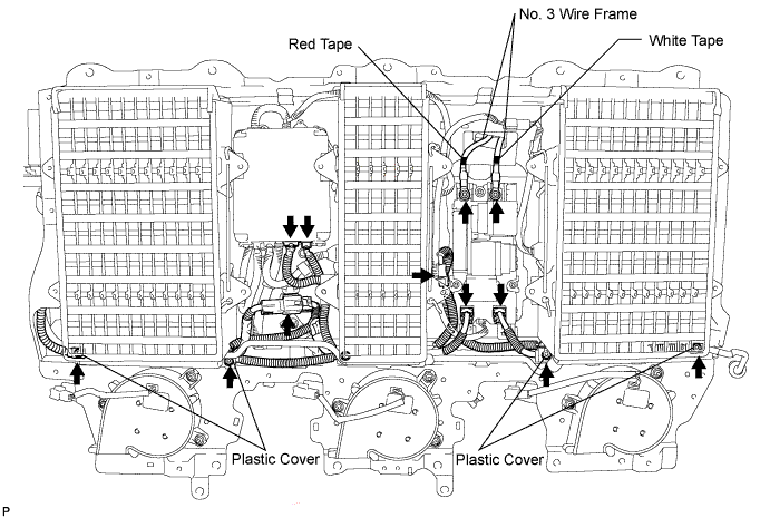
Check that each wire harness is being installed securely.
| 3. INSTALL BATTERY COVER SUB-ASSEMBLY |
Install the battery cover lock striker, then push the button to lock.
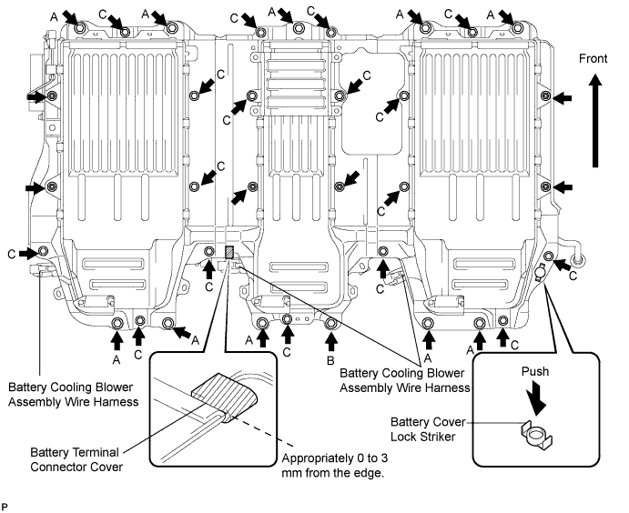
Install the battery cover with the 28 bolts and 6 nuts.
Install a new battery terminal connector cover (the cover fits over the upper and lower surfaces of the flange).
| 4. INSTALL HV BATTERY SERVICE HOLE COVER |
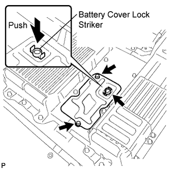 |
Install the battery cover lock striker, then push the button to lock.
Install the battery service hole cover with the 2 bolts.
| 5. INSTALL BATTERY CARRIER DUCT |
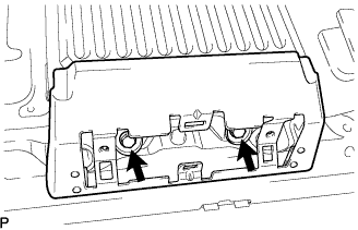 |
Install the battery carrier duct RH with the 2 bolts.
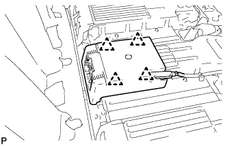 |
Install the battery cover sub-assembly with the 4 clips.
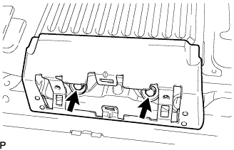 |
Install the battery carrier duct LH with the 2 bolts.
| 6. INSTALL REAR CENTER INNER SEAT BELT |
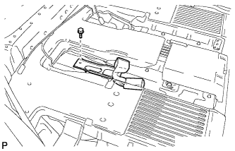 |
Install the rear center seat inner belt assembly with the bolt.
| 7. INSTALL NO. 3 FLOOR BOARD (w/ Rear No. 2 Seat) |
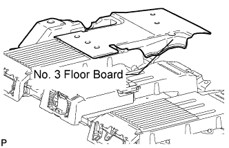 |
Install the No. 3 floor board.
| 8. INSTALL NO. 2 FLOOR BOARD (w/ Rear No. 2 Seat) |
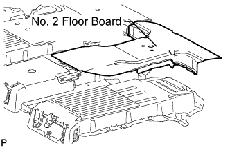 |
Install the No. 2 floor board.
| 9. INSTALL NO. 1 FLOOR BOARD (w/ Rear No. 2 Seat) |
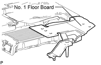 |
Install the No. 1 floor board.
| 10. INSTALL NO. 3 FLOOR BOARD (w/o Rear No. 2 Seat) |
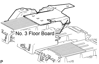 |
Install the No. 3 floor board.
| 11. INSTALL NO. 2 FLOOR BOARD (w/o Rear No. 2 Seat) |
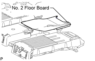 |
Install the No. 2 floor board.
| 12. INSTALL NO. 1 FLOOR BOARD (w/o Rear No. 2 Seat) |
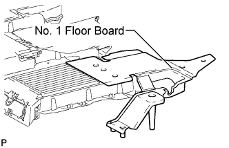 |
Install the No. 1 floor board.
| 13. INSTALL NO. 1 HV BATTERY TRAY |
Apply butyl tape to the No. 1 HV battery tray.
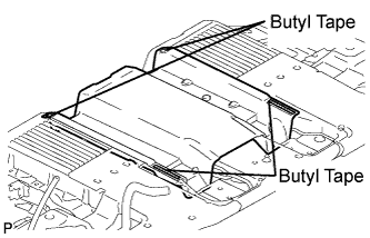 |
Install the No. 1 HV battery tray.
| 14. INSTALL FRONT FLOOR CARPET ASSEMBLY |
Install the front floor carpet.
| 15. INSTALL CENTER AIR INTAKE COVER |
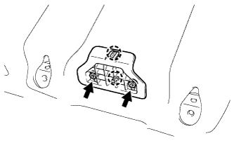 |
Install the air intake cover with the 2 screws.
Install the 2 hole covers.
| 16. INSTALL AIR INTAKE COVER |
Install the air intake cover RH.
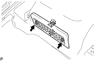 |
Install the air intake cover RH with the 2 screws.
Install the 2 hole covers.
Install the air intake cover LH.
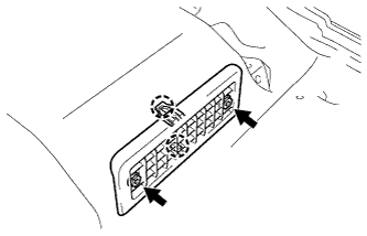 |
Install the air intake cover LH with the 2 screws.
Install the 2 hole covers.
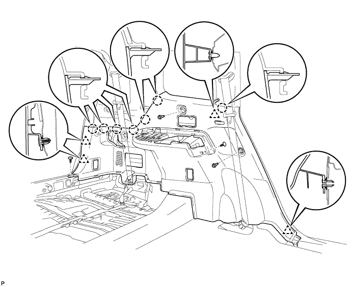
| 17. INSTALL DECK TRIM SIDE PANEL ASSEMBLY LH |
Engage the 4 clips and the 7 claws.
Install the 2 clips.
Install the deck trim side panel assembly LH with the 2 bolts.
| 18. CONNECT REAR NO. 1 SEAT OUTER BELT ASSEMBLY LH |
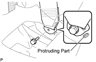 |
Connect the floor anchor end of the rear No. 1 seat outer belt assembly and install the bolt.
| 19. INSTALL FRONT DECK SIDE TRIM COVER LH |
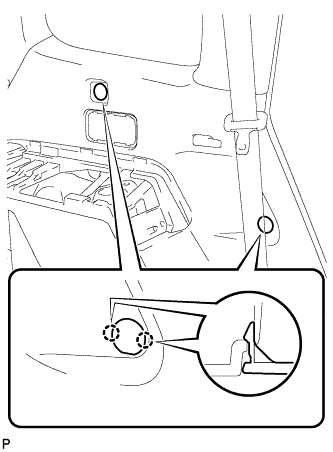 |
Engage the 4 claws and install the 2 front deck side trim covers LH.
| 20. INSTALL NO. 2 DECK SIDE TRIM HOOK |
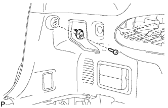 |
Install the No. 2 deck side trim hook with the screw.
| 21. INSTALL ROPE HOOK ASSEMBLY (for LH Side) |
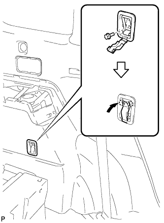 |
for Front Side:
Install the rope hook assembly with the bolt.
Engage the 2 claws.
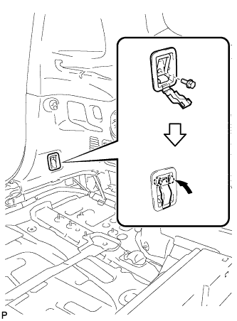 |
for Rear Side:
Install the rope hook assembly with the bolt.
Engage the 2 claws.
| 22. INSTALL REAR DECK TRIM COVER (w/o Remote Folding Function) |
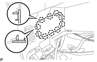 |
Engage the 10 claws and install the rear deck trim cover.
| 23. INSTALL RECLINING REMOTE CONTROL LEVER BEZEL LH (w/ Remote Folding Function) |
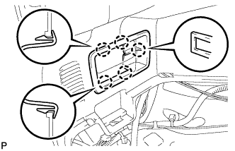 |
Engage the 5 claws and install the reclining remote control bezel lever LH.
| 24. INSTALL REAR POWER OUTLET SOCKET COVER |
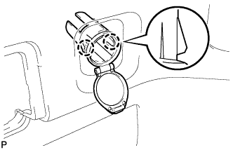 |
Engage the 2 claws and install the rear power outlet socket cover.
| 25. INSTALL REAR POWER POINT SOCKET ASSEMBLY |
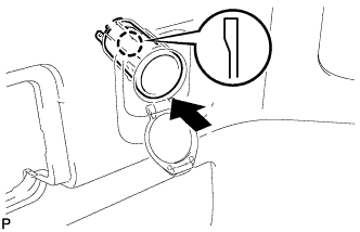 |
Engage the claw and install the rear power point socket assembly.
Connect the connector.
| 26. INSTALL REAR COMBINATION LIGHT SERVICE COVER LH |
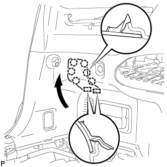 |
Engage the 2 guides and 6 claws, and install the rear combination light service cover LH.
| 27. INSTALL SIDE TRIM COVER LH (w/o Rear Seat Entertainment System) |
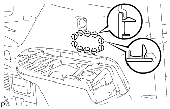 |
Engage the 10 claws and install the side trim cover LH.
| 28. INSTALL POWER OUTLET SOCKET BEZEL (w/ Rear Seat Entertainment System) |
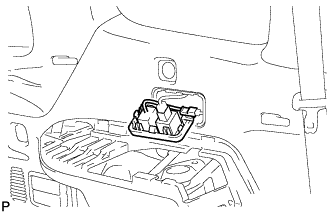 |
Connect each connector.
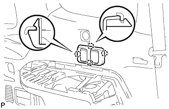 |
Engage the 4 claws and install the power outlet socket bezel.
| 29. INSTALL DECK SIDE TRIM LH |
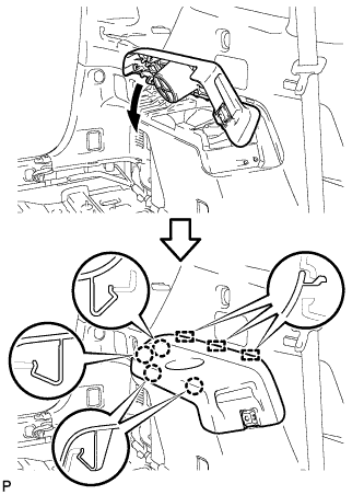 |
Engage the 3 guides and 4 claws as shown in the illustration.
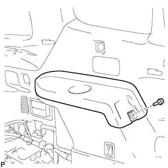 |
Install the deck side trim LH with the bolt.
| 30. INSTALL DECK SIDE TRIM COVER LH |
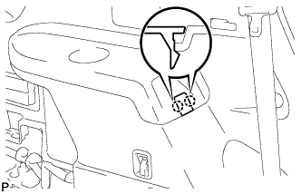 |
Engage the 2 claws and install the deck side trim cover LH.
| 31. INSTALL ROOF SIDE INNER GARNISH ASSEMBLY RH (w/o Rear No. 2 Seat) |
| 32. INSTALL ROOF SIDE INNER GARNISH ASSEMBLY RH (w/ Rear No. 2 Seat) |
| 33. INSTALL QUARTER PILLAR GARNISH RH |
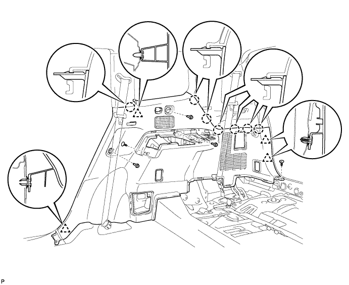
| 34. INSTALL DECK TRIM SIDE PANEL ASSEMBLY RH |
Engage the 4 clips and the 7 claws.
Install the 2 clips.
Install the deck trim side panel assembly RH with the 3 bolts.
| 35. CONNECT REAR NO. 1 SEAT OUTER BELT ASSEMBLY RH |
| 36. INSTALL FRONT DECK SIDE TRIM COVER RH |
| 37. INSTALL NO. 1 LUGGAGE COMPARTMENT TRIM HOOK |
| 38. INSTALL ROPE HOOK ASSEMBLY (for RH Side) |
| 39. INSTALL REAR COMBINATION LIGHT SERVICE COVER RH |
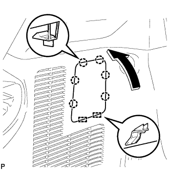 |
Engage the 2 guides and 6 claws, and install the rear combination light service cover RH.
| 40. INSTALL REAR ROOM TEMPERATURE SENSOR (w/ Rear Automatic Air Conditioning System) |
Connect the connector.
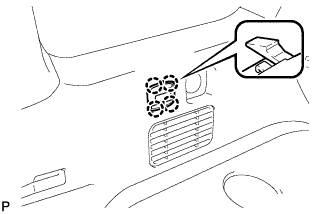 |
Engage the 4 claws and install the rear room temperature sensor.
| 41. INSTALL SIDE TRIM COVER RH (w/o Rear Automatic Air Conditioning System) |
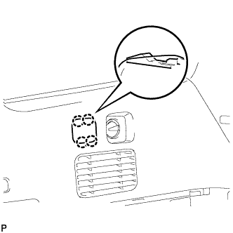 |
Engage the 4 claws, and install the side trim cover RH.
| 42. INSTALL DECK SIDE TRIM RH |
| 43. INSTALL DECK SIDE TRIM COVER RH |
| 44. INSTALL REAR SEAT SIDE GARNISH CAP (w/o Rear Air Conditioning System) |
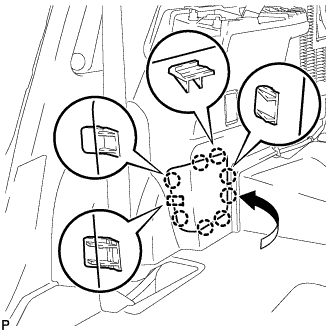 |
Engage the guide and the 8 claws, and install the rear seat side garnish cap.
| 45. INSTALL REAR SEAT SIDE GARNISH CAP (w/ Rear Automatic Air Conditioning System) |
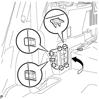 |
Engage the guide and the 6 claws.
Install the rear seat side garnish cap with the screw.
| 46. INSTALL REAR FLOOR FINISH PLATE |
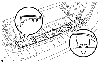 |
Engage the 4 clips and the 4 claws, and install the rear floor finish plate.
| 47. INSTALL REAR NO. 2 SEAT ASSEMBLY (w/ Rear No. 2 Seat) |
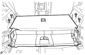 |
Install the rear No. 2 seat assembly with the 4 bolts.
| 48. CONNECT REAR SEAT LAP TYPE BELT ASSEMBLY LH (w/ Rear No. 2 Seat) |
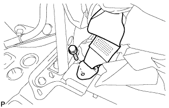 |
Install the rear seat lap type belt assembly LH with the bolt.
| 49. CONNECT REAR SEAT LAP TYPE BELT ASSEMBLY RH (w/ Rear No. 2 Seat) |
Install the rear seat lap type belt assembly RH with the bolt.
| 50. INSTALL REAR NO. 2 SEAT INNER BELT ASSEMBLY (w/ Rear No. 2 Seat) |
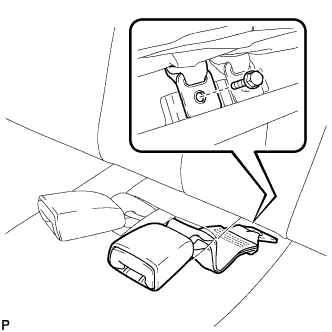 |
Install the rear No. 2 seat inner belt assembly with the bolt.
| 51. INSTALL DECK FLOOR BOARD ASSEMBLY (w/o Rear No. 2 Seat) |
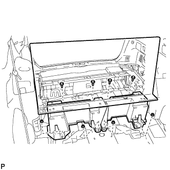 |
Install the deck floor board assembly with the 4 nuts and 4 bolts.
| 52. INSTALL REAR MAT |
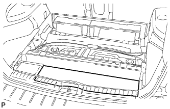 |
Install the rear mat.
| 53. INSTALL DECK FLOOR BOARD ASSEMBLY (w/ Rear No. 2 Seat) |
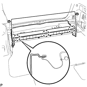 |
Install the 2 nuts and the deck floor board assembly.
Engage the 3 claws.
| 54. INSTALL DECK SIDE TRIM BOX LH |
Install the deck side trim box LH as shown in the illustration.
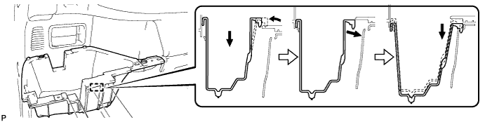
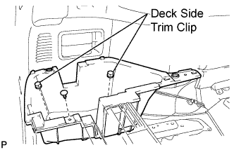 |
Install the 2 deck side trim clip and the clips.
| 55. INSTALL REAR SEAT SIDE COVER LH (w/ Rear No. 2 Seat) |
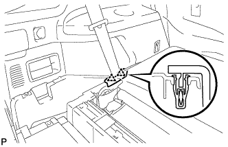 |
Engage the 2 clips and install the rear seat side cover LH.
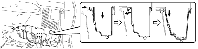
| 56. INSTALL DECK SIDE TRIM BOX RH |
Install the deck side trim box RH as shown in the illustration.
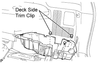 |
Install the 2 deck side trim clip and the clips.
| 57. INSTALL JACK CARRIER ASSEMBLY |
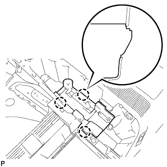 |
Engage the 3 claws, and install the jack carrier assembly.
| 58. INSTALL JACK ASSEMBLY |
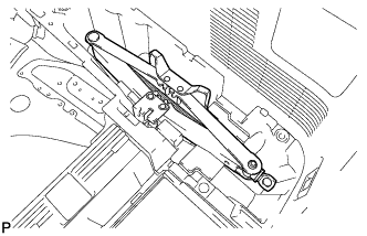 |
Install the jack assembly.
| 59. INSTALL JACK CARRIER CUSHION |
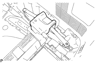 |
Install the jack carrier cushion.
| 60. INSTALL JACK CARRIER SUPPORT |
| 61. INSTALL REAR SEAT SIDE COVER RH (w/ Rear No. 2 Seat) |
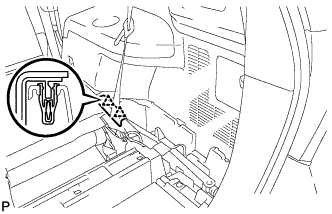 |
Engage the 2 clips and install the rear seat side cover RH.
| 62. INSTALL REAR NO. 1 FLOOR BOARD (w/o Rear No. 2 Seat) |
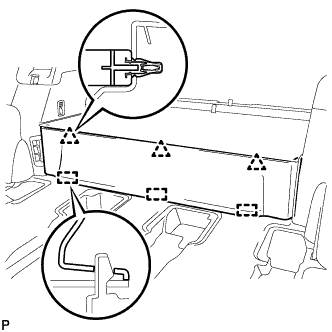 |
Engage the 3 guides and 3 clips and install the rear No. 1 floor board.
| 63. INSTALL TONNEAU COVER ASSEMBLY (w/ Tonneau Cover) |
Install the tonneau cover assembly.
| 64. INSTALL NO. 2 DECK BOARD SUB-ASSEMBLY |
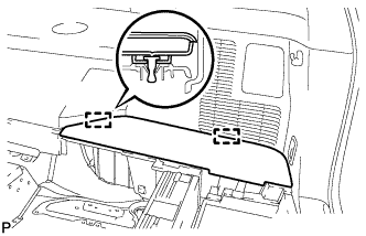 |
Engage the 2 guides and install the No. 2 deck board sub-assembly.
| 65. INSTALL NO. 3 DECK BOARD SUB-ASSEMBLY |
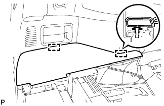 |
Engage the 2 guides and install the No. 3 deck board sub-assembly.
| 66. INSTALL DECK BOARD ASSEMBLY |
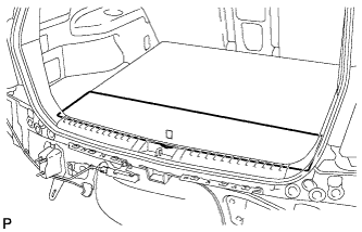 |
Install the deck board assembly.
| 67. INSTALL REAR NO. 1 SEAT ASSEMBLY (for RH Side) |
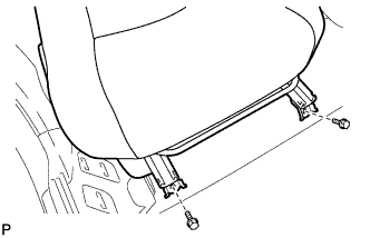 |
Temporarily install the 2 bolts on the front side of the seat.
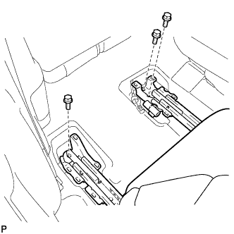 |
Temporarily install the 3 bolts on the rear side of the seat.
Install the rear No. 1 seat assembly with the 5 bolts.
| 68. CONNECT REAR NO. 1 SEAT LOCK CABLE ASSEMBLY (w/ Remote Folding Function) |
Remove the rear seat reclining control cable from the carpet hole.
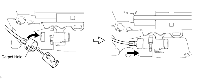
Connect the rear seat reclining control cable as shown in the illustration.
Connect the rear No. 1 seat lock cable assembly as shown in the illustration.
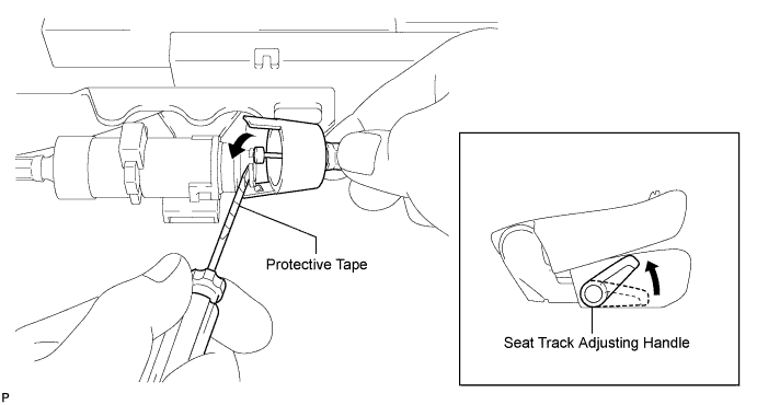
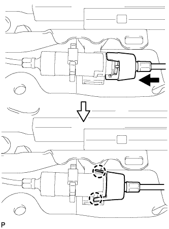 |
Engage the 2 claws and connect the rear No. 1 seat lock cable assembly as shown in the illustration.
Return the seatback to the upright position.
Pull up the adjuster's lock piece to lock it as shown in the illustration.
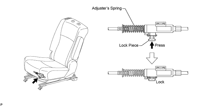
| 69. INSPECT REAR SEAT SLIDE ADJUSTER LOCK (for RH Side) |
Check that the left and right adjusters lock simultaneously when sliding the seat.
If the left and right adjusters do not lock simultaneously, adjust by loosening the bolts securing the seat.
| 70. INSTALL REAR SEAT LEG SIDE COVER (for RH Side) |
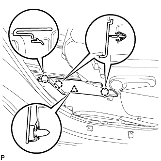 |
Engage the clip.
Engage the 3 claws and install the rear seat leg side cover.
| 71. INSTALL REAR INNER TRACK BRACKET COVER (for RH Side) |
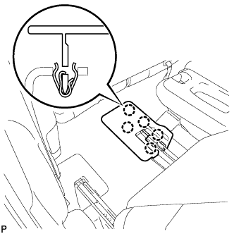 |
Engage the 5 claws and install the rear inner track bracket cover.
| 72. INSTALL REAR OUTER TRACK BRACKET COVER (for RH Side) |
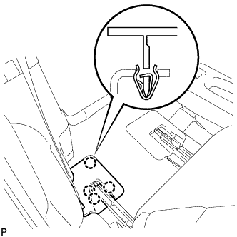 |
Engage the 4 claws and install the rear outer track bracket cover.
| 73. INSTALL REAR SEAT TRACK BRACKET COVER |
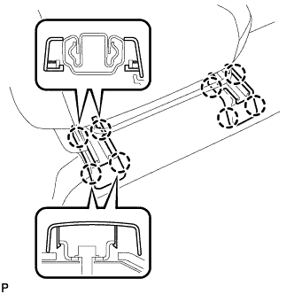 |
Engage the 8 claws and install the 2 seat track bracket covers.
| 74. INSTALL REAR SEAT HEADREST ASSEMBLY (for RH Side) |
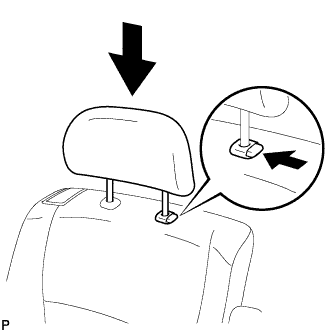 |
Install the rear seat headrest assembly as shown in the illustration.
| 75. INSTALL REAR NO. 1 SEAT ASSEMBLY (for LH Side) |
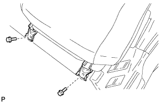 |
Temporarily install the 2 bolts on the front side of the seat.
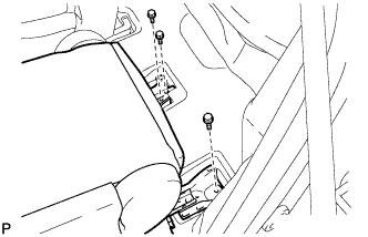 |
Temporarily install the 3 bolts on the rear side of the seat.
Install the rear No. 1 seat assembly with the 5 bolts.
| 76. INSTALL REAR NO. 1 SEAT LOCK CABLE ASSEMBLY (w/ Remote Folding Function) |
Remove the rear seat reclining control cable from the carpet hole.
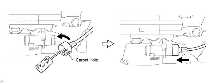
Connect the rear seat reclining control cable as shown in the illustration.
Connect the rear No. 1 seat lock cable assembly as shown in the illustration.
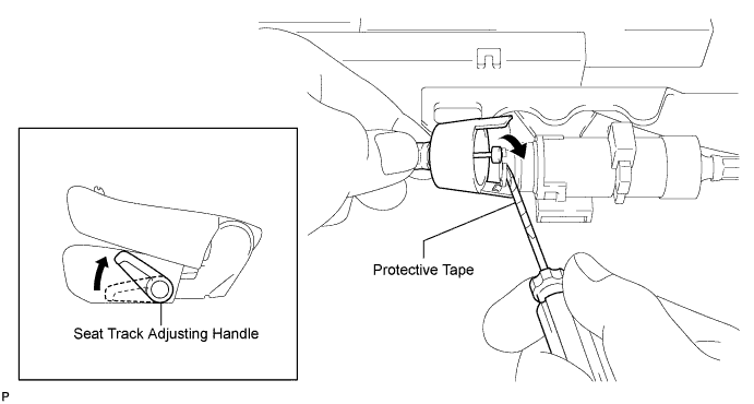
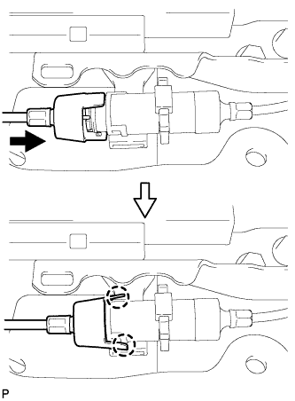 |
Engage the 2 claws and connect the rear No. 1 seat lock cable assembly as shown in the illustration.
Return the seatback to the upright position.
Pull up the adjuster's lock piece to lock it as shown in the illustration.
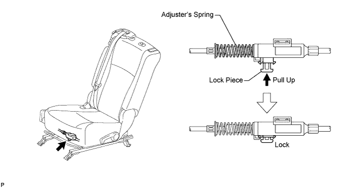
| 77. INSTALL REAR SEAT SLIDE ADJUSTER LOCK (for LH Side) |
Check that the left and right adjusters lock simultaneously when sliding the seat.
If the left and right adjusters do not lock simultaneously, adjust by loosening the bolts securing the seat.
| 78. INSTALL REAR SEAT LEG SIDE COVER (for LH Side) |
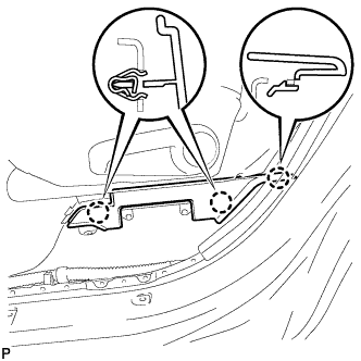 |
Engage the 3 claws and install the rear seat leg side cover.
| 79. INSTALL RECLINING HINGE COVER LH |
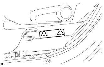 |
Engage the 2 clips and install the reclining hinge cover LH.
| 80. INSTALL REAR INNER TRACK BRACKET COVER (for LH Side) |
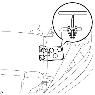 |
Engage the 5 claws and install the rear inner track bracket cover.
| 81. INSTALL REAR OUTER TRACK BRACKET COVER (for LH Side) |
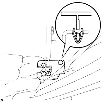 |
Engage the 4 claws and install the rear outer track bracket cover.
| 82. INSTALL REAR SEAT TRACK BRACKET COVER (for LH Side) |
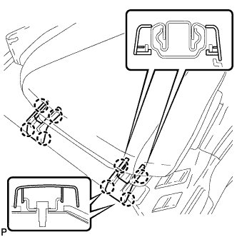 |
Engage the 8 claws and install the 2 rear seat track bracket covers.
| 83. INSTALL REAR SEAT HEADREST ASSEMBLY (for LH Side) |
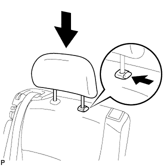 |
Install the rear seat headrest assembly as shown in the illustration.
| 84. REMOVE REAR CENTER SEAT ASSEMBLY |
| 85. INSTALL SERVICE PLUG GRIP |
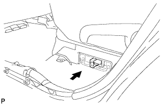 |
Wear insulated gloves, then insert the service plug.
Push down on the grip to lock.
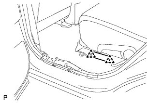 |
Close the reclining hinge cover.
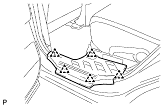 |
Close the rear door scuff plate LH.
| 86. CONNECT CABLE TO NEGATIVE BATTERY TERMINAL |
| 87. PERFORM INITIALIZATION |