 |
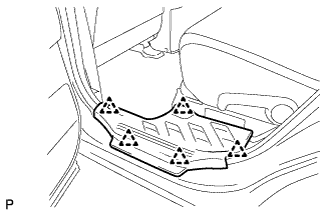
Remove the 5 clips and door scuff plate LH.
BATTERY SMART UNIT > REMOVAL |
| 1. PRECAUTION |
| 2. READ OUTPUT DTC |
Check for DTCs.
| 3. DISCONNECT CABLE FROM NEGATIVE BATTERY TERMINAL |
| 4. REMOVE SERVICE PLUG GRIP |
|
Remove the 5 clips and door scuff plate LH.
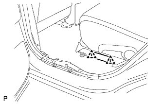 |
Remove the 2 clips and reclining hinge cover.
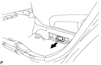 |
Wear insulated glove and remove the service plug grip, after sliding up the lever of the service plug grip.
| 5. REMOVE NO. 2 ENGINE ROOM SIDE COVER LH |
| 6. REMOVE COOL AIR INTAKE DUCT SEAL |
| 7. REMOVE AIR CLEANER CAP SUB-ASSEMBLY |
| 8. REMOVE AIR CLEANER CASE SUB-ASSEMBLY |
| 9. SEPARATE INVERTER RESERVE TANK SUB-ASSEMBLY |
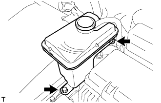 |
Remove the 2 bolts and inverter reserve tank sub-assembly.
| 10. REMOVE INVERTER COVER |
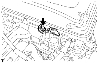 |
Remove the bolt and interlock bracket.
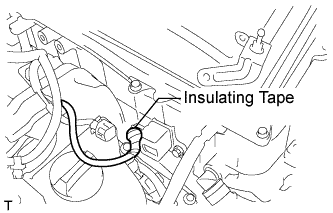 |
Insulate the removed terminal with insulating tape.
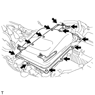 |
Remove the 12 bolts and inverter cover.
| 11. CHECK TERMINAL VOLTAGE |
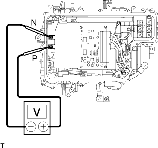 |
Using the voltmeter, measure the voltage between the terminals of the 2 phase connectors (N-P).
| 12. INSTALL INVERTER COVER |
|
Install the inverter cover with the 12 bolts to the inverter with converter assembly.
|
Install the interlock bracket with the bolt to the inverter with converter assembly.
| 13. INSTALL INVERTER RESERVE TANK SUB-ASSEMBLY |
|
Install the inverter reserve tank to the inverter with converter assembly with the 2 bolts.
| 14. INSTALL AIR CLEANER CASE SUB-ASSEMBLY |
| 15. INSTALL AIR CLEANER CAP SUB-ASSEMBLY |
| 16. INSTALL COOL AIR INTAKE DUCT SEAL |
| 17. INSTALL NO. 2 ENGINE ROOM SIDE COVER LH |
| 18. REMOVE REAR CENTER SEAT ASSEMBLY |
| 19. REMOVE REAR SEAT HEADREST ASSEMBLY |
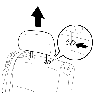 |
Press the headrest support button and pull up the headrest to its highest position as shown in the illustration.
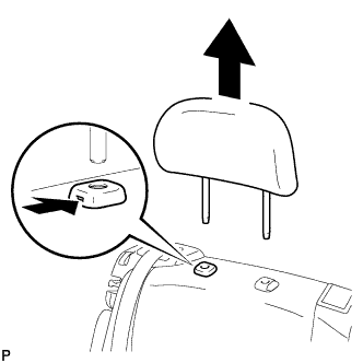 |
Insert a finger or screwdriver into the hole to release the lock. Pull the headrest up as shown in the illustration to remove it.
| 20. REMOVE REAR SEAT TRACK BRACKET COVER (for LH Side) |
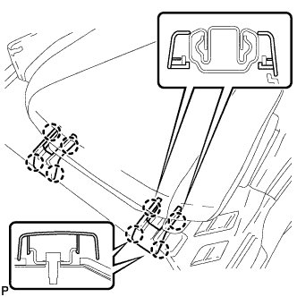 |
Disengage the 8 claws and remove the 2 rear seat track bracket covers.
| 21. REMOVE REAR OUTER TRACK BRACKET COVER (for LH Side) |
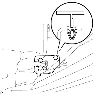 |
Disengage the 4 claws and remove the rear outer track bracket cover.
| 22. REMOVE REAR INNER TRACK BRACKET COVER (for LH Side) |
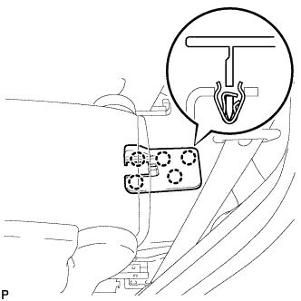 |
Disengage the 5 claws and remove the rear inner track bracket cover.
| 23. REMOVE RECLINING HINGE COVER LH |
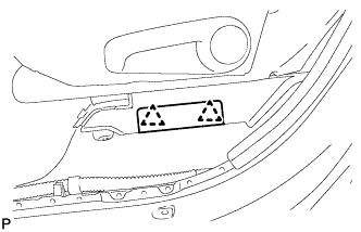 |
Disengage the 2 clips and remove the reclining hinge cover LH.
| 24. REMOVE REAR SEAT LEG SIDE COVER (for LH Side) |
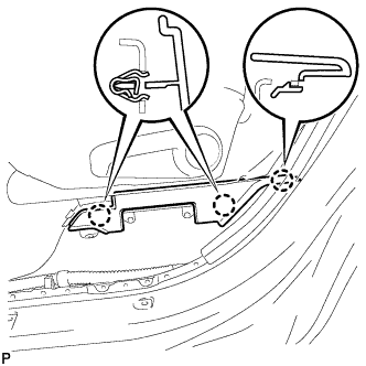 |
Disengage the 3 claws and remove the rear seat leg side cover.
| 25. DISCONNECT REAR NO. 1 SEAT LOCK CABLE ASSEMBLY (w/ Remote Folding Function) |
Pull down the adjuster's lock piece to release the lock as shown in the illustration.
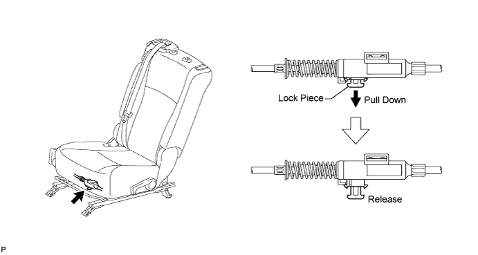
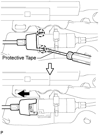 |
Using a screwdriver wrapped with protective tape, disengage the 2 claws as shown in the illustration.
Lift up the seat track adjusting handle to the uppermost position and hold the handle in this position as shown in the illustration.
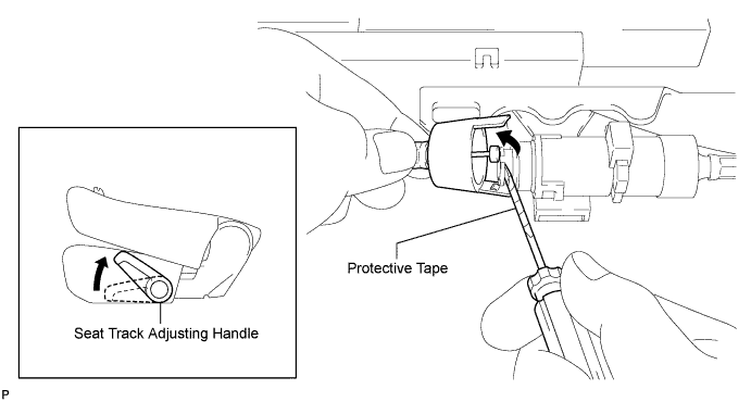
Using a screwdriver wrapped with protective tape, disconnect the rear No. 1 seat lock cable assembly as shown in the illustration.
Using a screwdriver wrapped with protective tape, disconnect the rear seat reclining control cable as shown in the illustration.
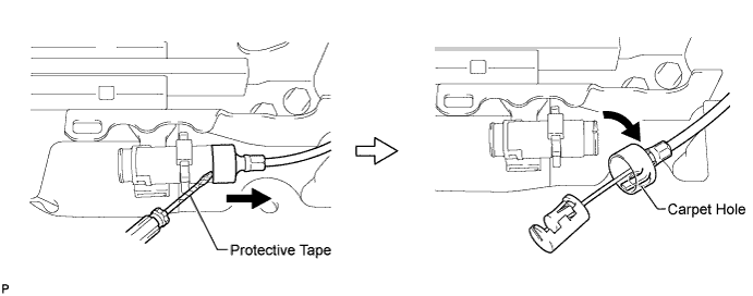
Secure the rear seat reclining control cable with the carpet hole as shown in the illustration.
| 26. REMOVE REAR NO. 1 SEAT ASSEMBLY (for LH Side) |
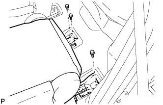 |
Remove the 3 bolts on the rear side of the seat.
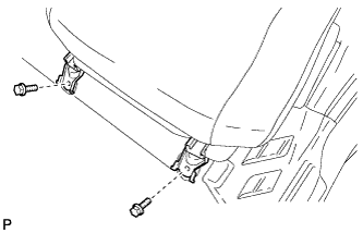 |
Remove the 2 bolts on the front side of the seat and the rear No. 1 seat assembly.
| 27. REMOVE REAR SEAT HEADREST ASSEMBLY (for RH Side) |
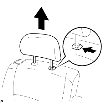 |
Press the headrest support button and pull up the headrest to its highest position as shown in the illustration.
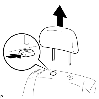 |
Insert a finger or screwdriver into the hole to release the lock. Pull the headrest up as shown in the illustration to remove it.
| 28. REMOVE REAR SEAT TRACK BRACKET COVER (for RH Side) |
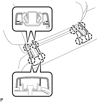 |
Disengage the 8 claws and remove the 2 rear seat track bracket covers.
| 29. REMOVE REAR OUTER TRACK BRACKET COVER (for RH Side) |
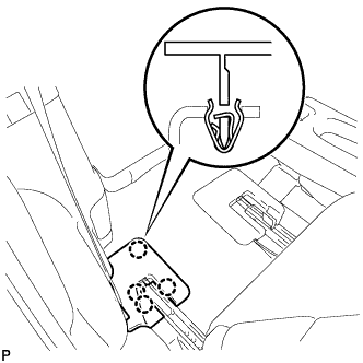 |
Disengage the 4 claws and remove the rear outer track bracket cover.
| 30. REMOVE REAR INNER TRACK BRACKET COVER (for RH Side) |
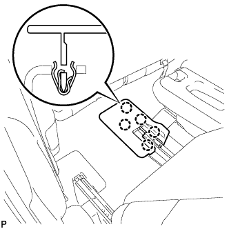 |
Disengage the 5 claws and remove the rear inner track bracket cover.
| 31. REMOVE REAR SEAT LEG SIDE COVER (for RH Side) |
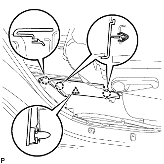 |
Disengage the 3 claws.
Disengage the clip and remove the rear seat leg side cover.
| 32. REMOVE REAR NO. 1 SEAT LOCK CABLE ASSEMBLY (w/ Remote Folding Function) |
Pull down the adjuster's lock piece to release the lock as shown in the illustration.
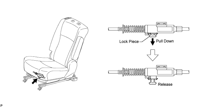
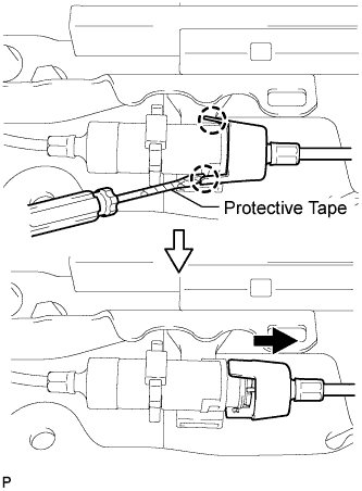 |
Using a screwdriver wrapped with protective tape, disengage the 2 claws as shown in the illustration.
Lift up the seat track adjusting handle to the uppermost position and hold the handle in this position as shown in the illustration.
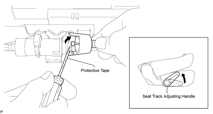
Using a screwdriver wrapped with protective tape, disconnect the rear No. 1 seat lock cable assembly as shown in the illustration.
Using a screwdriver wrapped with protective tape, disconnect the rear seat reclining control cable as shown in the illustration.
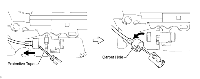
Secure the rear seat reclining control cable with the carpet hole as shown in the illustration.
| 33. REMOVE REAR NO. 1 SEAT ASSEMBLY (for RH Side) |
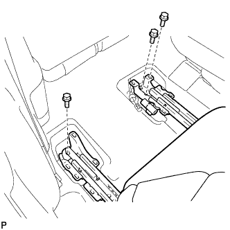 |
Remove the 3 bolts on the rear side of the seat.
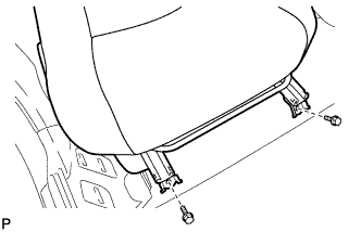 |
Remove the 2 bolts on the front side of the seat and the rear No. 1 seat assembly.
| 34. REMOVE DECK BOARD ASSEMBLY |
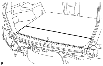 |
Remove the deck board assembly.
| 35. REMOVE NO. 3 DECK BOARD SUB-ASSEMBLY |
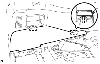 |
Disengage the 2 guides and remove the No. 3 deck board sub-assembly.
| 36. REMOVE NO. 2 DECK BOARD SUB-ASSEMBLY |
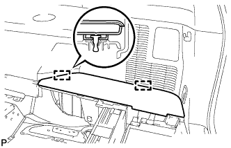 |
Disengage the 2 guides and remove the No. 2 deck board sub-assembly.
| 37. REMOVE TONNEAU COVER ASSEMBLY (w/ Tonneau Cover) |
Remove the tonneau cover assembly.
| 38. REMOVE REAR NO. 1 FLOOR BOARD (w/o Rear No. 2 Seat) |
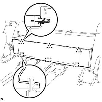 |
Disengage the 3 clips and the 3 guides, and remove the rear No. 1 floor board.
| 39. REMOVE REAR SEAT SIDE COVER LH (w/ Rear No. 2 Seat) |
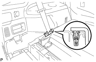 |
Disengage the 2 clips and remove the rear seat side cover LH.
| 40. REMOVE DECK SIDE TRIM BOX LH |
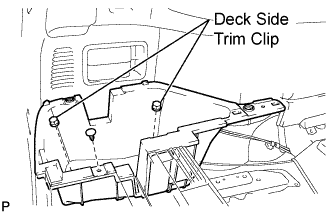 |
Remove the 2 deck side trim clips and clip.
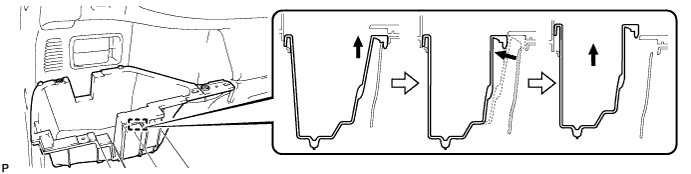
Remove the deck side trim box LH as shown in the illustration.
| 41. REMOVE REAR SEAT SIDE COVER RH (w/ Rear No. 2 Seat) |
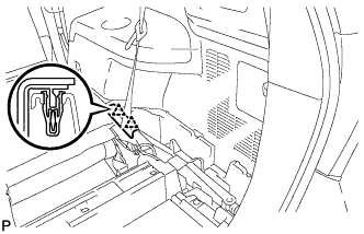 |
Disengage the 2 clips and remove the rear seat side cover RH.
| 42. REMOVE JACK CARRIER SUPPORT |
| 43. REMOVE JACK CARRIER CUSHION |
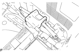 |
Remove the jack carrier cushion.
| 44. REMOVE JACK ASSEMBLY |
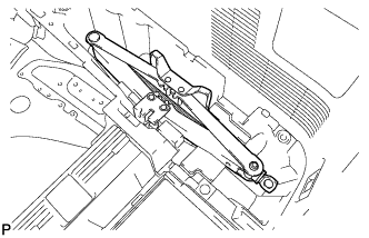 |
Remove the jack assembly.
| 45. REMOVE JACK CARRIER ASSEMBLY |
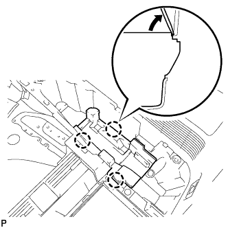 |
Using a screwdriver, disengage the 3 claws and remove the jack carrier assembly.
| 46. REMOVE DECK SIDE TRIM BOX RH |
|
Using a screwdriver, disengage the 3 claws and remove the jack carrier assembly.
| 47. REMOVE DECK FLOOR BOARD ASSEMBLY (w/o Rear No. 2 Seat) |
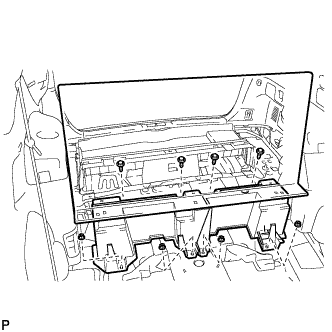 |
Remove the 4 bolts and 4 nuts.
Remove the deck floor board assembly.
| 48. REMOVE REAR MAT |
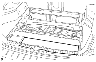 |
Remove the rear mat.
| 49. REMOVE DECK FLOOR BOARD ASSEMBLY (w/ Rear No. 2 Seat) |
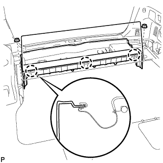 |
Disengage the 3 claws.
Remove the 2 nuts and the deck floor board assembly.
| 50. REMOVE REAR DECK FLOOR BOX (w/o Rear No. 2 Seat) |
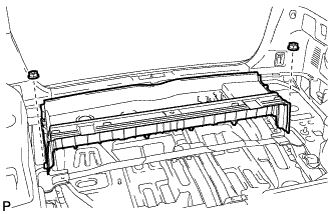 |
Remove the 2 nuts and the deck floor box.
| 51. REMOVE REAR NO. 2 SEAT INNER BELT ASSEMBLY (w/ Rear No. 2 Seat) |
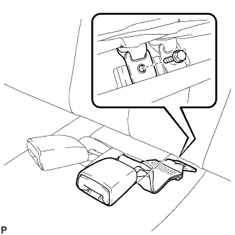 |
Remove the bolt and rear No. 2 seat inner belt assembly.
| 52. REMOVE REAR SEAT LAP TYPE BELT ASSEMBLY LH (w/ Rear No. 2 Seat) |
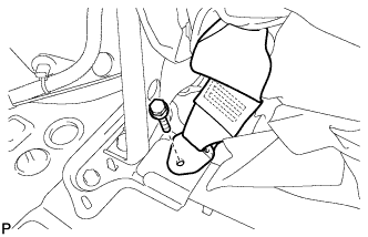 |
Remove the bolt and disconnect the rear seat lap type belt assembly LH.
| 53. REMOVE REAR SEAT LAP TYPE BELT ASSEMBLY RH (w/ Rear No. 2 Seat) |
| 54. REMOVE REAR NO. 2 SEAT ASSEMBLY (w/ Rear No. 2 Seat) |
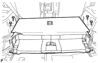 |
Remove the 4 bolts and the rear No. 2 seat assembly.
| 55. REMOVE REAR FLOOR FINISH PLATE |
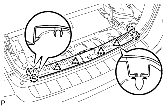 |
Disengage the 4 clips and the 4 claws, and remove the rear floor finish plate.
| 56. REMOVE DECK SIDE TRIM COVER LH |
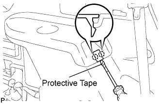 |
Using a screwdriver, disengage the 2 claws and remove the deck side trim cover LH.
| 57. REMOVE DECK SIDE TRIM LH |
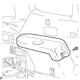 |
Remove the bolt.
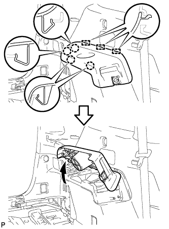 |
Disengage the 4 claws and the 3 guides, and remove the deck side trim LH as shown in the illustration.
| 58. REMOVE SIDE TRIM COVER LH (w/o Rear Seat Entertainment System) |
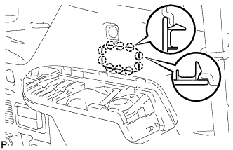 |
Disengage the 10 claws and remove the side trim cover LH.
| 59. REMOVE POWER OUTLET SOCKET BEZEL (w/ Rear Seat Entertainment System) |
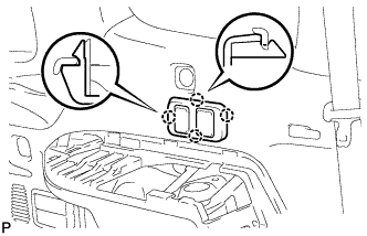 |
Disengage the 4 claws.
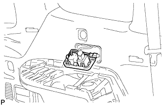 |
Disconnect each connector and remove the power outlet socket bezel.
| 60. REMOVE REAR COMBINATION LIGHT SERVICE COVER LH |
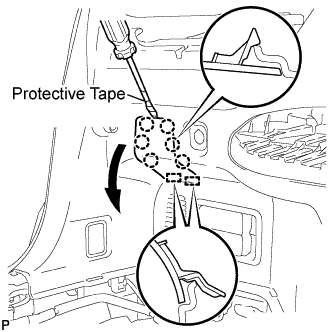 |
Using a screwdriver, disengage the 6 claws and 2 guides, and remove the rear combination light service cover LH.
| 61. REMOVE REAR POWER POINT SOCKET ASSEMBLY |
Disconnect the connector.
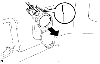 |
Disengage the claw and remove the rear power point socket assembly.
| 62. REMOVE REAR POWER OUTLET SOCKET COVER |
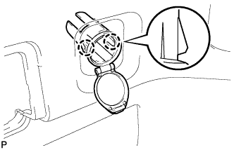 |
Disengage the 2 claws and remove the rear power outlet socket cover.
| 63. REMOVE REAR DECK TRIM COVER (w/o Remote Folding Function) |
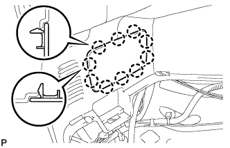 |
Disengage the 10 claws and remove the rear deck trim cover.
| 64. REMOVE RECLINING REMOTE CONTROL LEVER BEZEL LH (w/ Remote Folding Function) |
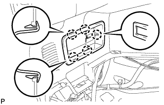 |
Disengage the 5 claws and remove the reclining remote control lever bezel LH.
| 65. REMOVE ROPE HOOK ASSEMBLY (for LH Side) |
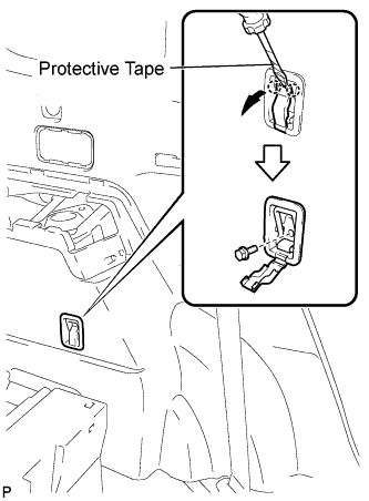 |
for Front Side:
Using a screwdriver, disengage the 2 claws.
Remove the bolt and the rope hook assembly.
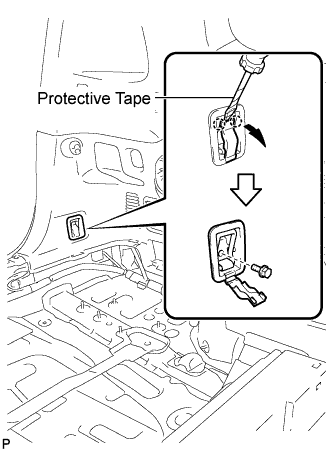 |
for Rear Side:
Using a screwdriver, disengage the 2 claws.
Remove the bolt and rope hook assembly.
| 66. REMOVE NO. 2 DECK SIDE TRIM HOOK |
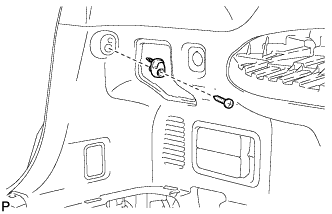 |
Remove the screw and the No. 2 deck side trim hook.
| 67. REMOVE FRONT DECK SIDE TRIM COVER LH |
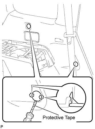 |
Using a screwdriver, disengage the 4 claws and remove the 2 front deck side trim covers LH.
| 68. DISCONNECT REAR NO. 1 SEAT OUTER BELT ASSEMBLY |
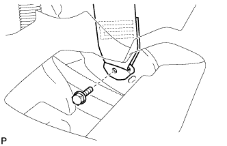 |
Remove the bolt and disconnect the floor end of the rear No. 1 seat outer belt assembly.
| 69. REMOVE DECK TRIM SIDE PANEL ASSEMBLY LH |
Remove the 2 bolts.
Remove the 2 clips.
Disengage the 7 claws and 4 clips, and remove the deck trim side panel assembly LH.
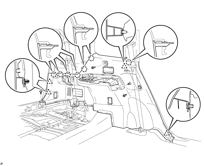
| 70. REMOVE QUARTER PILLAR GARNISH LH |
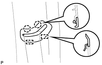 |
Disengage the 2 claws and 2 guides, and remove the No. 1 seat outer belt guide.
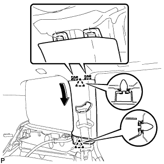 |
Disengage the 2 clips and the 2 guides, and remove the quarter pillar garnish LH.
| 71. REMOVE ROOF SIDE INNER GARNISH ASSEMBLY LH (w/o Power Back Door) |
w/o Rear No. 2 Seat:
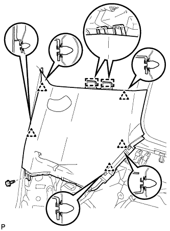 |
Remove the bolt.
Disengage the 5 clips and 2 guides, and remove the roof side inner garnish assembly LH.
w/ Rear No. 2 Seat:
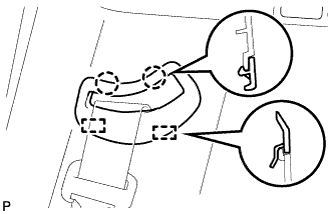 |
Disengage the 2 claws and 2 guides, and remove the rear No. 2 seat outer belt guide.
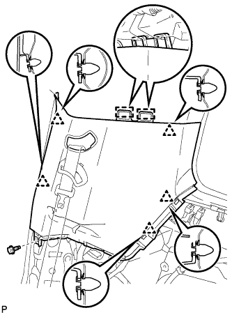 |
Remove the bolt.
Disengage the 5 clips and 2 guides, and remove the roof side inner garnish assembly LH.
| 72. REMOVE ROOF SIDE INNER GARNISH ASSEMBLY LH (w/ Power Back Door) |
w/o Rear No. 2 Seat:
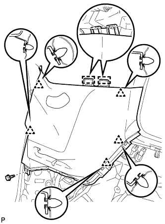 |
Remove the bolt.
Disengage the 5 clips and 2 guides, and remove the roof side inner garnish assembly LH.
w/ Rear No. 2 Seat:
|
Disengage the 2 claws and 2 guides, and remove the rear No. 2 seat outer belt guide.
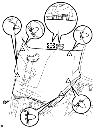 |
Remove the bolt.
Disengage the 5 clips and 2 guides, and remove the roof side inner garnish assembly LH.
| 73. REMOVE REAR SEAT SIDE GARNISH CAP (w/o Rear Air Conditioning System) |
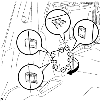 |
Disengage the 8 claws and guide, and remove the rear seat side garnish cap.
| 74. REMOVE REAR SEAT SIDE GARNISH CAP (w/ Rear Air Conditioning System) |
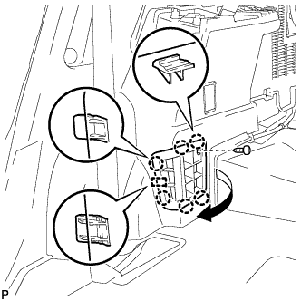 |
Remove the screw.
Disengage the 6 claws and the guide, and remove the rear seat side garnish cap.
| 75. REMOVE DECK SIDE TRIM COVER RH |
| 76. REMOVE DECK SIDE TRIM RH |
| 77. REMOVE SIDE TRIM COVER RH (w/o Rear Automatic Air Conditioning System) |
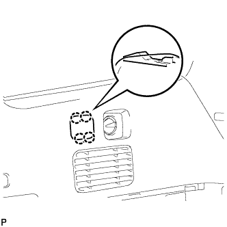 |
Disengage the 4 claws and remove the side trim cover RH.
| 78. REMOVE REAR ROOM TEMPERATURE SENSOR (w/ Rear Automatic Air Conditioning System) |
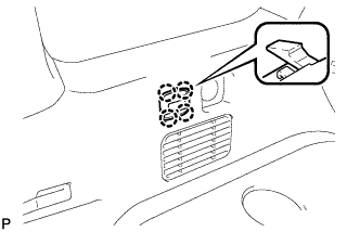 |
Disengage the 4 claws and remove the rear room temperature sensor.
Disconnect the connector.
| 79. REMOVE REAR COMBINATION LIGHT SERVICE COVER RH |
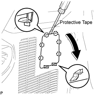 |
Using a screwdriver, disengage the 6 claws and the 2 guides, and remove the rear combination light service cover RH.
| 80. REMOVE ROPE HOOK ASSEMBLY (for RH Side) |
| 81. REMOVE NO. 1 LUGGAGE COMPARTMENT TRIM HOOK |
| 82. REMOVE FRONT DECK SIDE TRIM COVER RH |
| 83. REMOVE REAR NO. 1 SEAT OUTER BELT ASSEMBLY RH |
| 84. REMOVE DECK TRIM SIDE PANEL ASSEMBLY RH |
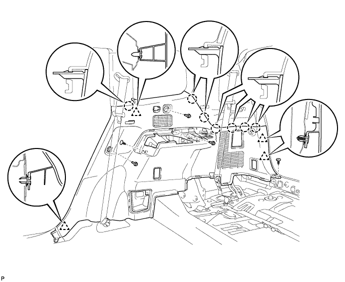
Remove the 3 bolts.
Remove the 2 clips.
Disengage the 7 claws and 4 clips, and remove the deck trim side panel assembly RH.
| 85. REMOVE AIR INTAKE COVER |
Remove the air intake cover LH.
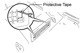 |
Release the claw by using a screwdriver with the tip taped, and remove its 2 hole covers.
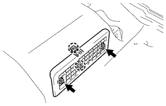 |
Remove the 2 screws, then release the 2 claws and remove the air intake cover LH.
Remove the air intake cover RH.
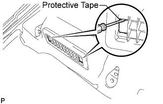 |
Release the claw by using a screwdriver with its tip taped, and remove the 2 hole covers.
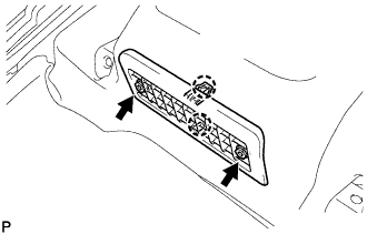 |
Remove the 2 screws, then release the 2 claws and remove the air intake cover RH.
| 86. REMOVE CENTER AIR INTAKE COVER |
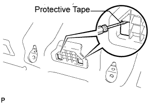 |
Release the claw by using a screwdriver with the tip taped, and remove its 2 hole covers.
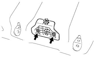 |
Remove the 2 screws, then release the 2 claws and remove the center air intake cover.
| 87. SEPARATE FRONT FLOOR CARPET ASSEMBLY |
Turn back the front floor carpet assembly.
| 88. REMOVE NO. 1 HV BATTERY TRAY |
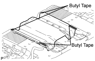 |
Remove the No. 1 HV battery tray.
| 89. REMOVE NO. 1 FLOOR BOARD (w/ Rear No. 2 Seat) |
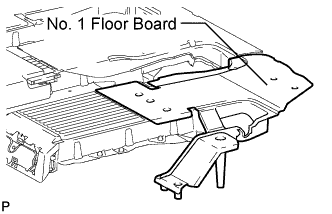 |
Remove the No. 1 floor board.
| 90. REMOVE NO. 2 FLOOR BOARD (w/ Rear No. 2 Seat) |
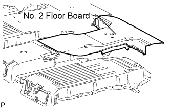 |
Remove the No. 2 floor board.
| 91. REMOVE NO. 3 FLOOR BOARD (w/ Rear No. 2 Seat) |
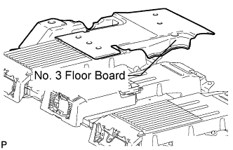 |
Remove the No. 3 floor board.
| 92. REMOVE NO. 1 FLOOR BOARD (w/o Rear No. 2 Seat) |
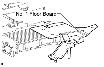 |
Remove the No. 1 floor board.
| 93. REMOVE NO. 2 FLOOR BOARD (w/o Rear No. 2 Seat) |
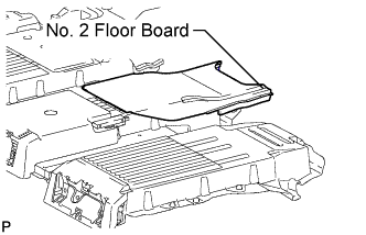 |
Remove the No. 2 floor board.
| 94. REMOVE NO. 3 FLOOR BOARD (w/o Rear No. 2 Seat) |
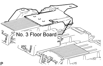 |
Remove the No. 3 floor board.
| 95. REMOVE REAR CENTER INNER SEAT BELT |
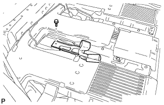 |
Remove the bolt and the rear center seat inner belt assembly.
| 96. REMOVE BATTERY CARRIER DUCT |
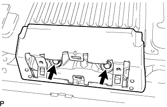 |
Remove the 2 bolts and battery carrier duct LH.
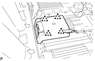 |
Remove the 4 clips and floor spacer board.
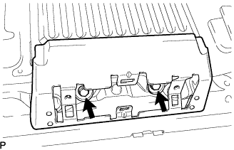 |
Remove the 2 bolts and battery carrier duct RH.
| 97. REMOVE HV BATTERY SERVICE HOLE COVER |
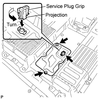 |
Using the service plug grip, remove the battery cover lock striker.
Remove the 2 bolts and battery service hole cover.
| 98. REMOVE BATTERY COVER SUB-ASSEMBLY |
Using the service plug grip, remove the battery cover lock striker.
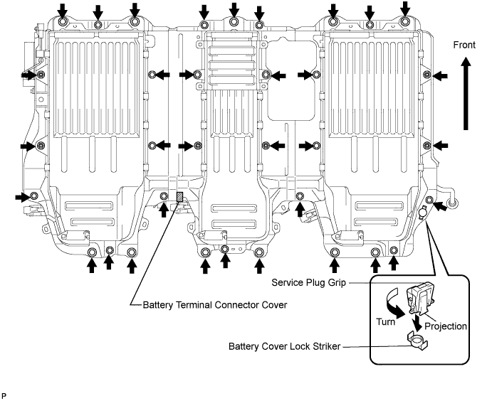
Remove the battery terminal connector cover.
Remove the 28 bolts, 6 nuts and battery cover.
| 99. REMOVE BATTERY SMART UNIT |
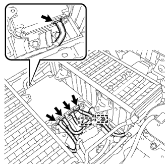 |
Disconnect the 5 connectors and 2 clamps.
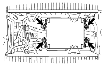 |
Remove the 4 bolts and battery smart unit.