Home › ENGINE › 3MZ-FE ENGINE CONTROL SYSTEM › SFI SYSTEM

SFI SYSTEM > Fuel Pump Control Circuit

for Preparation Click here


DESCRIPTION

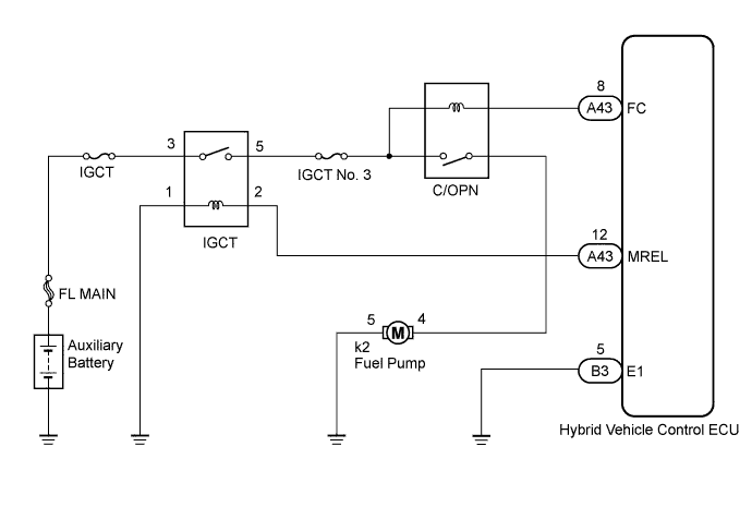
The fuel pump is operated by the engine control system according to the vehicle running condition. After the engine control system receives the engine start requirement signal from the hybrid vehicle control system, an NE signal comes in immediately when the engine is cranked by MG1 (basically, the fuel pump can operate while the NE signal is generated).
The engine control system grounds the FC terminal line after receiving the NE signal. It causes to energize the coil in the circuit opening relay, and the current flows to the fuel pump.
When the signal to stop the engine comes from the hybrid vehicle control system to the engine control system, or when the fuel cut operation is performed such as decelerating by the engine brake, the fuel pump is stopped.

WIRING DIAGRAM


A179786E01


INSPECTION PROCEDURE

1.PERFORM ACTIVE TEST USING TECHSTREAM (OPERATE C/OPN RELAY)
  1. Connect the Techstream to the DLC3.

  1. Turn the power switch on (IG) and turn the Techstream on.

  1. Enter the following menus: Powertrain / Engine and ECT / Active Test / Control the Fuel Pump / Speed.

  1. Check the operation of the relay while operating it using the Techstream.

    OK:
    Operating noise can be heard from the relay.


NG
Go to step 3
OK


2.INSPECT FUEL PUMP
  1. Inspect fuel pump resistance (Click here).


NG
REPLACE FUEL PUMP (Click here)
OK

PROCEED TO NEXT CIRCUIT INSPECTION SHOWN IN PROBLEM SYMPTOMS TABLE (Click here)  

3.INSPECT ECM POWER SOURCE CIRCUIT


NG
REPAIR OR REPLACE POWER SOURCE CIRCUIT COMPONENTS
OK


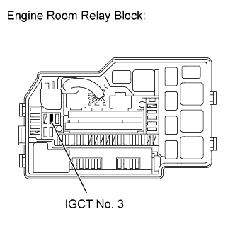
4.INSPECT FUSE (IGCT NO. 3 FUSE)


    A179777E06
  1. Remove the IGCT No. 3 fuse from the engine room relay block.

  1. Measure the resistance in the IGCT No. 3 fuse.

    Standard resistance:
    Below 1 Ω

  1. Reinstall the fuse.


NG
REPLACE FUSE (IGCT NO. 3 FUSE)
OK


5.INSPECT ENGINE ROOM JUNCTION BLOCK ASSEMBLY (C/OPN RELAY)
  1. Inspect the C/OPN relay (Click here).


NG
REPLACE ENGINE ROOM JUNCTION BLOCK ASSEMBLY
OK


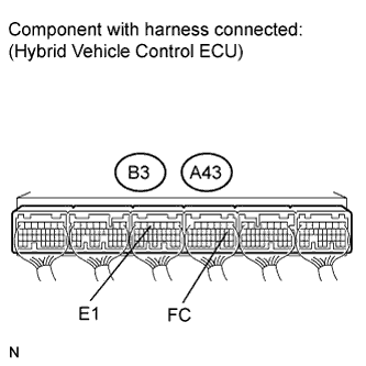
6.INSPECT HYBRID VEHICLE CONTROL ECU (FC VOLTAGE)


    A178675E08
  1. Turn the power switch on (IG).

  1. Measure the voltage according to the value(s) in the table below.

    Standard voltage:
    Tester Connection
    Condition
    Specified Condition
    A43-8 (FC) - B3-5 (E1)
    Power switch on (IG)
    11 to 14 V


NG
REPLACE HARNESS AND CONNECTOR (HYBRID VEHICLE CONTROL ECU - C/OPN RELAY)
OK

REPLACE HYBRID VEHICLE CONTROL ECU (Click here)