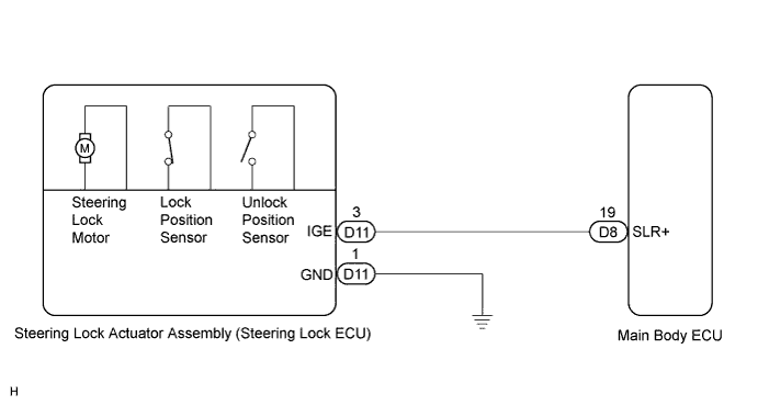
STEERING LOCK SYSTEM > Steering Lock Motor Drive Power Circuit |
| 1.CHECK VEHICLE CONDITION |
Check the problem symptom of the steering lock system.
| Condition | Proceed to |
| Steering lock cannot be released | A |
| Steering cannot be locked | B |
|
| ||||
| A | |
 |
| 2.READ VALUE USING TECHSTREAM |
Turn the power switch off.
Connect Techstream to the DLC3.
Turn the power switch on (IG).
Turn Techstream on.
Enter the following menus: Body Electrical / Smart Access / Data List.
Select the item below in the Data List, and read its value displayed on Techstream.
| Tester Display | Measurement Item/Range | Normal Condition | Diagnostic Note |
| Lock/Unlock Receive | Steering lock command reception record / YES or NO | YES: Steering lock / unlock signal received NO: Steering lock / unlock signal not received | - |
Check if a steering unlock command signal has been received.
|
| ||||
| OK | |
|
| 3.INSPECT STEERING LOCK ACTUATOR ASSEMBLY (STEERING LOCK ECU) |
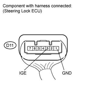 |
Measure the voltage according to the value(s) in the table below.
| Tester Connection | Switch Condition | Specified Condition |
| D11-3 (IGE) - D11-1 (GND) |
|
|
|
| ||||
| OK | ||
 | ||
| ||
| 4.CHECK HARNESS AND CONNECTOR (STEERING LOCK ACTUATOR ASSEMBLY - BODY GROUND) |
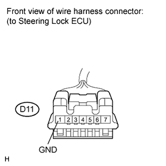 |
Disconnect the D11 connector from the steering lock actuator assembly.
Measure the resistance according to the value(s) in the table below.
| Tester Connection | Switch Condition | Specified Condition |
| D11-1 (GND) - Body ground | Always | Below 1 Ω |
|
| ||||
| OK | |
|
| 5.CHECK HARNESS AND CONNECTOR (STEERING LOCK ACTUATOR ASSEMBLY - MAIN BODY ECU) |
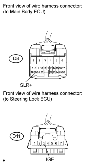 |
Disconnect the D8 connector from the main body ECU.
Measure the resistance according to the value(s) in the table below.
| Tester Connection | Switch Condition | Specified Condition |
| D11-3 (IGE) - D8-19 (SLR+) | Always | Below 1 Ω |
| D11-3 (IGE) - Body ground | Always | 10 kΩ or higher |
|
| ||||
| OK | ||
| ||
| ||
| 6.INSPECT STEERING LOCK ACTUATOR ASSEMBLY (STEERING LOCK ECU) |
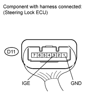 |
Measure the voltage according to the value(s) in the table below.
| Tester Connection | Condition | Specified Condition |
| D11-3 (IGE) - D11-1 (GND) | The specified condition should be checked after performing the following:
|
|
|
| ||||
| OK | ||
| ||
| ||
| 7.CHECK HARNESS AND CONNECTOR (STEERING LOCK ACTUATOR ASSEMBLY - MAIN BODY ECU) |
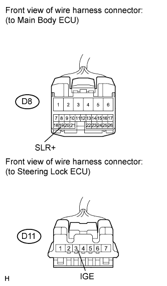 |
Disconnect the D11 connector from the steering lock actuator assembly.
Disconnect the D8 connector from the main body ECU.
Measure the resistance according to the value(s) in the table below.
| Tester Connection | Switch Condition | Specified Condition |
| D11-3 (IGE) - D8-19 (SLR+) | Always | Below 1 Ω |
| D11-3 (IGE) - Body ground | Always | 10 kΩ or higher |
|
| ||||
| OK | ||
| ||
| ||

