| B |  |
| GO TO DTC CHART (Click here) |
DTC P0A78-279 Drive Motor "A" Inverter Performance |
DTC P0A78-503 Drive Motor "A" Inverter Performance |
| DTC No. | INF Code | DTC Detection Condition | Trouble Area |
| P0A78 | 279 | Motor inverter overvoltage signal detection (overvoltage by inverter with converter assembly) |
|
| 503 | Motor inverter overvoltage signal detection (overvoltage by MG ECU malfunction) |
| Related DTCs | P0A78 (INF 279/503): Motor inverter / OVH detection (Over voltage High malfunction) |
| Required sensors / components | Motor inverter |
| Frequency of operation | Continuous |
| Duration | TMC's intellectual property |
| MIL operation | Immediately |
| Sequence of operation | None |
| The monitor will run whenever the DTCs listed are not present | TMC's intellectual property |
| Other conditions belong to TMC's intellectual property | - |
| Motor inverter | Overvoltage |
| Motor inverter | DTC P0A78 (INF 279/503) is not detected |
| 1.CHECK DTC OUTPUT (HV) |
Connect the Techstream to the DLC3.
Turn the power switch on (IG).
Select the following menu items: Powertrain / Hybrid Control / Trouble Codes.
Check if DTCs are output.
| Result | Proceed to |
| P0A78-279 or 503 only is output. | A |
| Any of the following DTCs are also output. | B |
| DTC No. | Relevant Diagnosis |
| P0A78-266, 280 | Drive Motor "A" Inverter Performance |
| P0A94-558, 559, 588, 589 | DC/DC Converter Performance |
| P0A95-123 | High Voltage Fuse |
| P0ADB-227 | Hybrid Battery Positive Contactor Circuit Stuck Open |
| P0ADC-226 | Hybrid Battery Positive Contactor Circuit Stuck Closed |
| P0ADF-229 | Hybrid Battery Negative Contactor Circuit Stuck Open |
| P0AE0-228 | Hybrid Battery Negative Contactor Circuit Stuck Closed |
| P3004-803 | Power Cable Malfunction |
|
| ||||
| A | |
 |
| 2.CHECK CONNECTOR CONNECTION CONDITION (MG ECU CONNECTOR) |
Turn the power switch off.
Remove the service plug grip (Click here).
Remove the inverter cover (Click here).
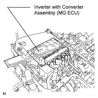 |
Check the connections of all MG ECU connectors.
|
| ||||
| OK | |
|
| 3.INSPECT HV RELAY ASSEMBLY (SMR2) |
Check that the service plug grip is not installed.
Remove the HV relay assembly from the vehicle (Click here).
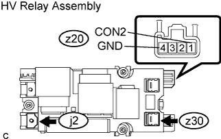 |
Measure the resistance according to the value(s) in the table below.
| Tester Condition | Condition | Specified Condition |
| z30-1 - j2-1 | Power switch off (Auxiliary battery voltage is applied between terminals z20-1 (CON2) and z20-4 (GND)) | Below 1 Ω |
Measure the resistance according to the value(s) in the table below.
| Tester Condition | Condition | Specified Condition |
| z20-1 (CON2) - z20-4 (GND) | Power switch off (-35 to 80°C (-31 to 176°F)) | 20 to 60 Ω |
|
| ||||
| OK | |
|
| 4.INSPECT HV RELAY ASSEMBLY (SMR3) |
Check that the service plug grip is not installed.
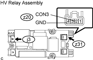 |
Measure the resistance according to the value(s) in the table below.
| Tester Condition | Condition | Specified Condition |
| z31-1 - j3-1 | Power switch off (Auxiliary battery voltage is applied between terminals z20-2 (CON3) and z20-4 (GND)) | Below 1 Ω |
Measure the resistance according to the value(s) in the table below.
| Tester Condition | Condition | Specified Condition |
| z20-2 (CON3) - z20-4 (GND) | Power switch off (-35 to 80°C (-31 to 176°F)) | 20 to 60 Ω |
|
| ||||
| OK | ||
 | ||
| ||