Home › HYBRID SYSTEM ยท P310 › HYBRID VEHICLE CONTROL › HYBRID CONTROL SYSTEM

DTC    P0A94-551    DC / DC Converter Performance

DTC    P0A94-552    DC / DC Converter Performance

for Preparation Click here


DESCRIPTION

Refer to the description of the boost converter .
If the boost converter detects a circuit malfunction, overheat, or internal short, it will transmit this information to the FCV terminal of the MG ECU via the boost converter fail signal line. The MG ECU monitors the boost converter fail signal line and detects the following malfunction.

DTC No.
INF Code
DTC Detection Condition
Trouble Area
P0A94
551
Open or short to GND in boost converter fail (FCV) signal line
Inverter with converter assembly (MG ECU)
552
Short to +B in boost converter fail (FCV) signal line

MONITOR DESCRIPTION

The MG ECU monitors the boost converter fail (FCV) signal line. If the MG ECU detects an open or short in the FCV signal circuit, the hybrid vehicle control ECU will illuminate the MIL and set a DTC.

MONITOR STRATEGY


Related DTCs
P0A94 (INF 551): Boost converter / Converter FCV malfunction (short to GND and disconnection)
P0A94 (INF 552): Boost converter / Converter FCV malfunction (short to +B)
Required sensors / components
Boost converter
Frequency of operation
Continuous
Duration
TMC's intellectual property
MIL operation
1 driving cycle
Sequence of operation
None

TYPICAL ENABLING CONDITIONS


The monitor will run whenever the DTCs listed are not present
TMC's intellectual property
Other conditions belong to TMC's intellectual property
-

TYPICAL MALFUNCTION THRESHOLDS


Boost converter fail signal circuit
Open or short

COMPONENT OPERATING RANGE


Boost converter
DTC P0A94 (INF 551/552) is not detected

INSPECTION PROCEDURE

CAUTION:
  1. Before inspecting the high-voltage system or disconnecting the low voltage connector of the inverter with converter assembly, take safety precautions such as wearing insulated gloves and removing the service plug grip to prevent electrical shocks. After removing the service plug grip, put it in your pocket to prevent other technicians from accidentally reconnecting it while you are working on the high-voltage system.
  2. After disconnecting the service plug grip, wait for at least 5 minutes before touching any of the high-voltage connectors or terminals. After waiting for 5 minutes, check the voltage at the terminals in the inspection point in the inverter with converter assembly. The voltage should be 0 V before beginning work.

HINT:
Waiting for at least 5 minutes is required to discharge the high-voltage capacitor inside the inverter with converter assembly.

1.CHECK CONNECTOR CONNECTION CONDITION (MG ECU CONNECTOR)

CAUTION:
Be sure to wear insulated gloves.

  1. Turn the power switch off.

  1. Remove the service plug grip (Click here).

    NOTICE:
    After removing the service plug grip, do not turn the power switch on (READY), unless instructed by the repair manual because this may cause a malfunction.

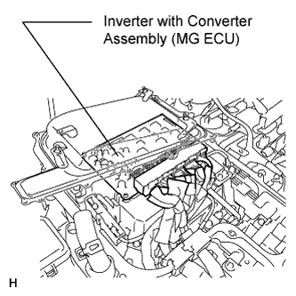
  1. Remove the inverter cover (Click here).

    NOTICE:
    1. Wrap the round interlock terminal for the inverter cover with insulating tape to prevent it from shorting to ground.
    2. Be sure to prevent coolant in the inverter reserve tank from entering the inverter.
    3. Removing the inverter cover causes the MG ECU board to be exposed. Therefore, temporarily install the inverter cover for each area to be inspected.


    A170989E01
  1. Check the connections of the MG ECU connectors.

    OK:
    The connectors are connected securely and there are no contact problems.


NG
CONNECT SECURELY
OK

REPLACE INVERTER WITH CONVERTER ASSEMBLY (Click here)