 |
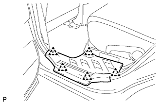
Remove the 5 clips and door scuff plate LH.
FRAME WIRE > REMOVAL |
| 1. PRECAUTION |
| 2. DISCONNECT CABLE FROM NEGATIVE BATTERY TERMINAL |
| 3. REMOVE SERVICE PLUG GRIP |
|
Remove the 5 clips and door scuff plate LH.
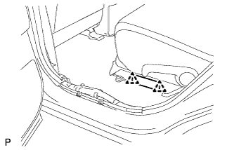 |
Remove the 2 clips and reclining hinge cover.
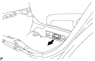 |
Wear insulated glove and remove the service plug grip, after sliding up the lever of the service plug grip.
| 4. REMOVE FRONT WIPER ARM AND BLADE ASSEMBLY LH |
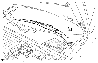 |
Remove the nut, and the front wiper arm and blade assembly LH.
| 5. REMOVE FRONT WIPER ARM AND BLADE ASSEMBLY RH |
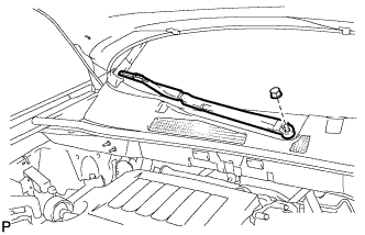 |
Remove the nut, and the front wiper arm and blade assembly RH.
| 6. REMOVE HOOD TO COWL TOP SEAL |
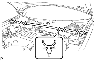 |
Disengage the 8 clips and remove the hood to cowl top seal.
| 7. REMOVE COWL TOP VENTILATOR LOUVER SUB-ASSEMBLY |
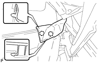 |
Disengage the 2 claws and disconnect the front fender to cowl side seal LH.
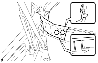 |
Disengage the 2 claws and disconnect the front fender to cowl side seal RH.
Remove the 2 clips.
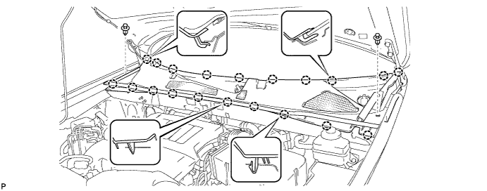
Disengage the 20 claws and remove the cowl top ventilator louver sub-assembly.
| 8. REMOVE WINDSHIELD WIPER MOTOR AND LINK ASSEMBLY |
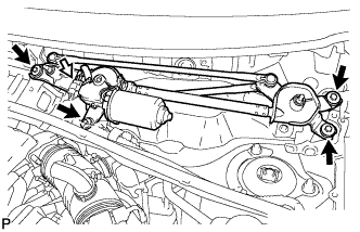 |
Disconnect the connector.
Remove the 4 bolts, and the windshield wiper motor and link assembly.
| 9. REMOVE OUTER COWL TOP PANEL SUB-ASSEMBLY |
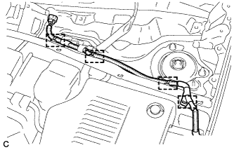 |
Disengage the 4 clamps and separate the wiper wire harness from the outer cowl top panel sub-assembly.
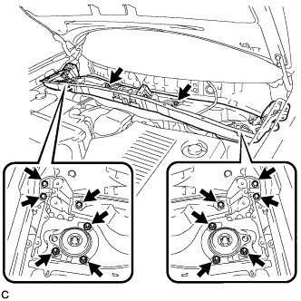 |
Remove the 8 bolts, 6 nuts, and the outer cowl top panel sub-assembly.
| 10. REMOVE HYBRID BATTERY SERVICE HOLE COVER |
| 11. DISCONNECT NO. 3 FRAME WIRE |
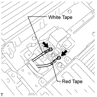 |
Remove the 2 nuts, and disconnect the No. 3 frame wire from the hybrid vehicle relay assembly.
| 12. REMOVE NO. 2 ENGINE ROOM SIDE COVER LH |
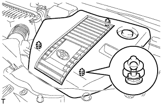 |
Remove the engine room side cover.
| 13. REMOVE AIR CLEANER CAP SUB-ASSEMBLY |
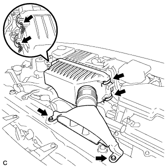 |
Remove the 2 bolts, 4 clamps and air cleaner cap sub-assembly.
Remove the air cleaner filter element from the air cleaner case.
| 14. REMOVE AIR CLEANER CASE SUB-ASSEMBLY |
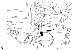 |
Separate the No. 1 ventilation hose.
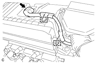 |
Disconnect the intake air flow meter connector.
Disconnect the 2 wire harness clamps from the air cleaner case sub-assembly.
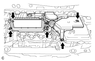 |
Remove the 5 bolts from the air cleaner case sub-assembly.
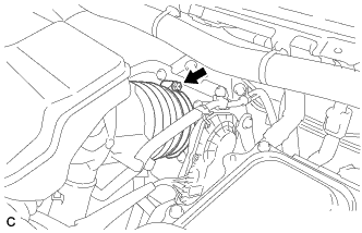 |
Loosen the hose clamp and separate the No. 1 air cleaner hose.
Remove the air cleaner case sub-assembly.
| 15. REMOVE INVERTER RESERVE TANK SUB-ASSEMBLY |
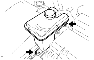 |
Remove the 2 bolts from the inverter reserve tank sub-assembly.
| 16. DISCONNECT NO. 2 ENGINE ROOM WIRE |
Remove the relay block cover.
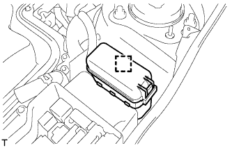 |
Disconnect the clamp, and release the engine room relay block assembly.
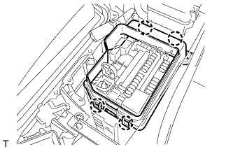 |
Disconnect the 4 claws, and disconnect the No. 2 relay block cover.
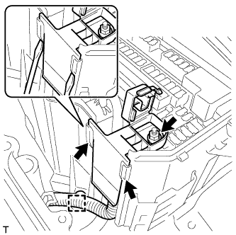 |
Remove the nut from the No. 2 engine room wire.
Release the 2 claws, and disconnect the No. 2 engine room wire.
Disconnect the clamp.
| 17. CHECK TERMINAL VOLTAGE |
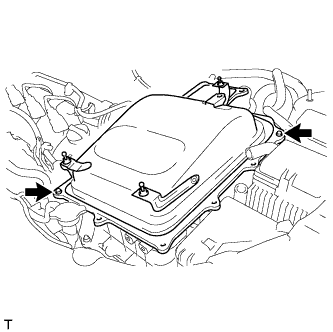 |
Temporarily install the inverter cover with the 2 bolts to prevent any foreign objects or waterdrops from entering the inverter with converter assembly.
| 18. DISCONNECT NO. 3 FRAME WIRE |
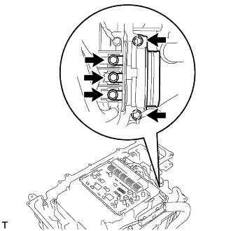 |
Remove the 5 bolts, and disconnect the No. 3 frame wire (high voltage cable of the rear motor (MGR)) to the inverter with converter assembly.
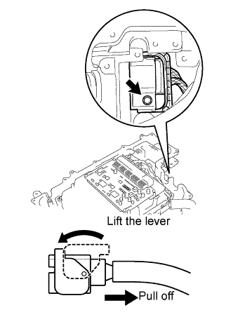 |
Remove the bolt and lift the lever to disconnect the No. 3 frame wire from the inverter with converter assembly.
| 19. INSTALL INVERTER COVER |
|
Temporarily install the inverter cover with the 2 bolts to prevent any foreign objects or waterdrops from entering the inverter with converter assembly.
| 20. REMOVE REAR ENGINE SERVICE COVER ASSEMBLY (w/ Rear Air Conditioning System) |
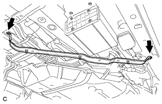 |
Remove the 2 bolts and rear engine service cover assembly.
| 21. REMOVE HEATER COVER (w/ Rear Air Conditioning System) |
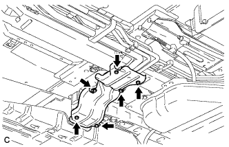 |
Remove the 6 bolts and heater cover.
| 22. SEPARATE AIR CONDITIONER ACCESSORY ASSEMBLY (w/ Rear Air Conditioning System) |
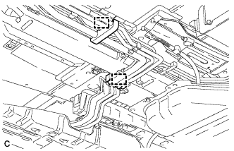 |
Separate the 2 clamps and air conditioner accessory assembly.
| 23. REMOVE WIRING HARNESS PROTECTOR |
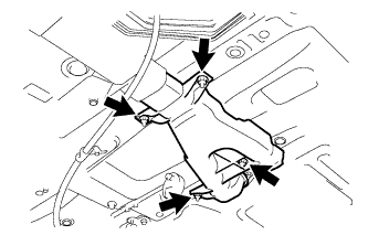 |
Remove the 4 nuts and wiring harness protector.
| 24. REMOVE NO. 3 FRAME WIRE |
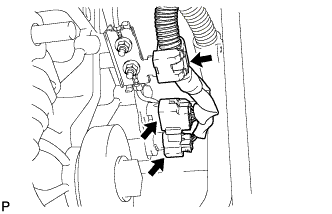 |
Disconnect the 2 connectors and clamp from the rear traction with transaxle motor assembly.
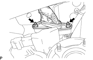 |
Remove the 2 nuts, and disconnect the No. 3 frame wire from the rear traction with transaxle motor assembly.
Remove the No. 3 frame wire.
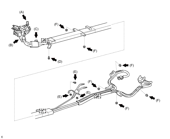
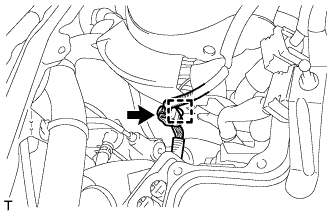 |
Disconnect the connector and clamp as shown in the illustration. (A)
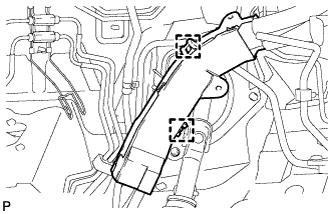 |
Disconnect the 2 clamps as shown in the illustration. (B)
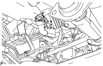 |
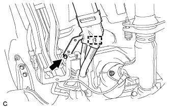
Disconnect the clamp as shown in the illustration. (C)
 |
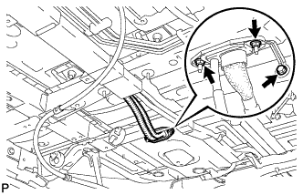
Disconnect the bolt and clamp as shown in the illustration. (D)
 |
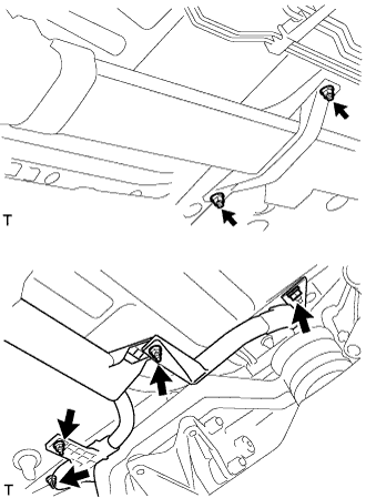
Remove the 2 nuts and bolt shown in the illustration and disconnect the No. 3 frame wire. (E)
 |
Remove the 6 nuts. (F)
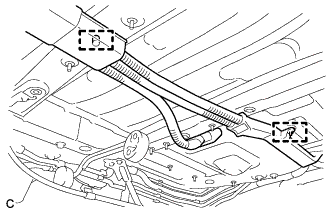 |
Remove the 2 clamps and No. 3 frame wire.