 |
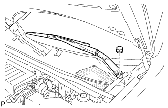
Remove the nut, and the front wiper arm and blade assembly LH.
CAMSHAFT (for Bank 1) > REMOVAL |
| 1. REMOVE FRONT WIPER ARM AND BLADE ASSEMBLY LH |
|
Remove the nut, and the front wiper arm and blade assembly LH.
| 2. REMOVE FRONT WIPER ARM AND BLADE ASSEMBLY RH |
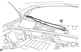 |
Remove the nut, and the front wiper arm and blade assembly RH.
| 3. REMOVE HOOD TO COWL TOP SEAL |
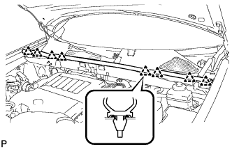 |
Disengage the 8 clips and remove the hood to cowl top seal.
| 4. REMOVE COWL TOP VENTILATOR LOUVER SUB-ASSEMBLY |
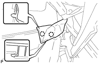 |
Disengage the 2 claws and disconnect the front fender to cowl side seal LH.
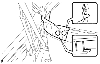 |
Disengage the 2 claws and disconnect the front fender to cowl side seal RH.
Remove the 2 clips.
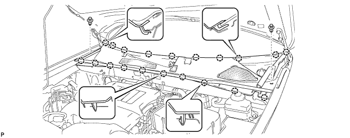
Disengage the 20 claws and remove the cowl top ventilator louver sub-assembly.
| 5. REMOVE WINDSHIELD WIPER MOTOR AND LINK ASSEMBLY |
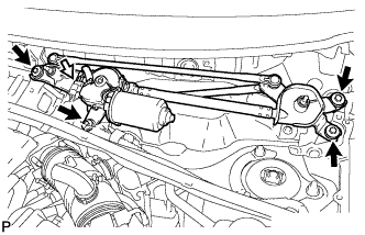 |
Disconnect the connector.
Remove the 4 bolts, and the windshield wiper motor and link assembly.
| 6. REMOVE OUTER COWL TOP PANEL SUB-ASSEMBLY |
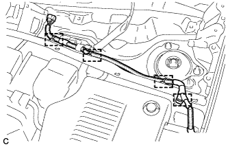 |
Disengage the 4 clamps and separate the wiper wire harness from the outer cowl top panel sub-assembly.
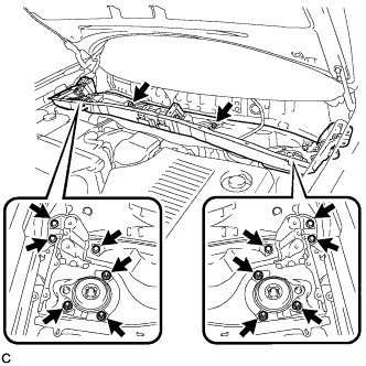 |
Remove the 8 bolts, 6 nuts, and the outer cowl top panel sub-assembly.
| 7. REMOVE NO. 2 ENGINE ROOM SIDE COVER LH |
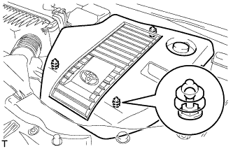 |
Remove the engine room side cover.
| 8. DRAIN COOLANT (for Engine) |
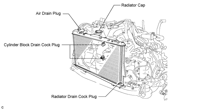
Loosen the radiator drain cock plug.
Loosen the cylinder block drain cock plugs.
Remove the radiator cap.
| 9. DRAIN ENGINE OIL |
Remove the oil filler cap.
Remove the oil drain plug and drain the oil into a container.
Clean and install the oil pan drain plug with a new gasket.
| 10. REMOVE FRONT WHEEL RH |
| 11. REMOVE NO. 1 ENGINE UNDER COVER |
Remove the 6 bolts, 2 screws, 2 clips and No. 1 engine under cover.
| 12. REMOVE FRONT FENDER LINER RH |
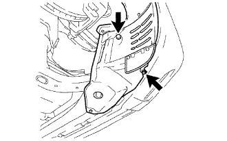 |
Remove the screw and clip, and separate the front fender liner.
| 13. REMOVE FRONT FENDER APRON SEAL RH |
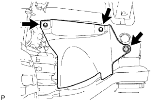 |
Remove the 2 bolts, clip and fender apron seal RH.
| 14. REMOVE BATTERY |
Disconnect the battery terminal.
Remove the bolt and battery clamp.
Remove the battery and battery tray.
| 15. REMOVE BATTERY CARRIER SUB-ASSEMBLY |
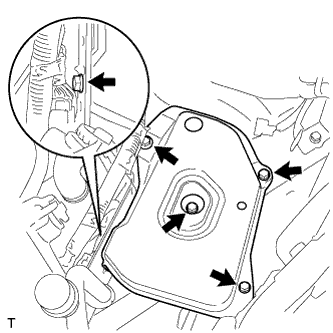 |
Remove the 5 bolts and battery carrier.
| 16. REMOVE AIR CLEANER CAP SUB-ASSEMBLY |
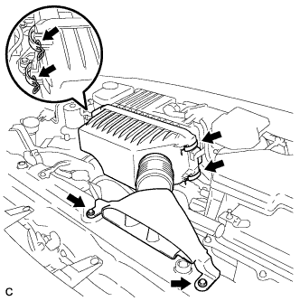 |
Remove the 2 bolts, 4 clamps and air cleaner cap sub-assembly.
Remove the air cleaner filter element from the air cleaner case.
| 17. REMOVE AIR CLEANER CASE SUB-ASSEMBLY |
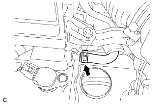 |
Separate the No. 1 ventilation hose.
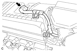 |
Disconnect the intake air flow meter connector.
Disconnect the 2 wire harness clamps from the air cleaner case sub-assembly.
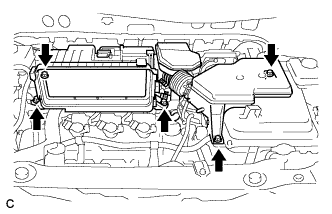 |
Remove the 5 bolts from the air cleaner case sub-assembly.
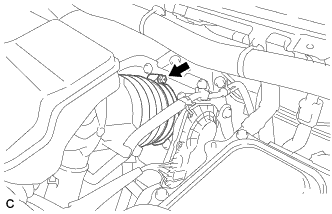 |
Loosen the hose clamp and separate the No. 1 air cleaner hose.
Remove the air cleaner case sub-assembly.
| 18. REMOVE EMISSION CONTROL VALVE SET |
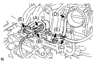 |
Disconnect the VSV connector (A).
Remove the wire harness clamp (B).
Disconnect the No. 1 fuel vapor feed hose (C).
Disconnect the No. 2 fuel vapor feed hose (D).
Remove the 2 nuts (E), then remove the emission control valve set.
| 19. REMOVE INTAKE AIR SURGE TANK |
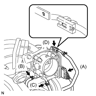 |
Disconnect the throttle motor connector (A).
Separate the No. 2 water by-pass hose (B).
Separate the No. 3 water by-pass hose (C).
Separate the fuel vapor feed hose (D).
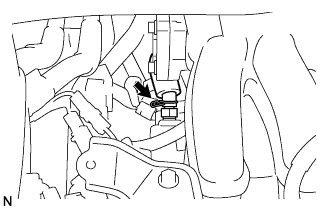 |
Disconnect the ventilation hose.
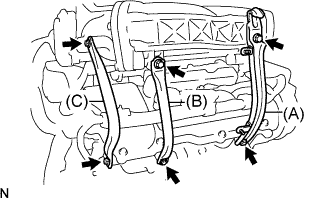 |
Remove the 2 bolts and No. 1 engine hanger (A).
Remove the 2 bolts and No. 1 surge tank stay (B).
Remove the 2 bolts and No. 2 surge tank stay (C).
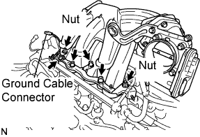 |
Disconnect the ground cable connector.
Using a socket hexagon wrench 8 mm, remove the 4 bolts.
Remove the 2 nuts, then remove the emission control valve bracket and the intake air surge tank.
Remove the gasket from the intake air surge tank.
| 20. REMOVE AIR CLEANER BRACKET |
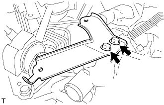 |
Remove the 2 bolts and air cleaner bracket.
| 21. SEPARATE BRAKE MASTER CYLINDER RESERVOIR SUB-ASSEMBLY |
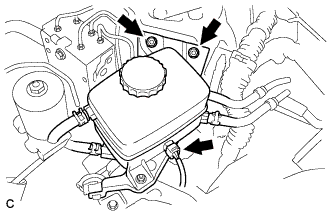 |
Disconnect the connector.
Remove the 2 nuts and separate the brake master cylinder reservoir.
| 22. REMOVE ENGINE MOVING CONTROL ROD |
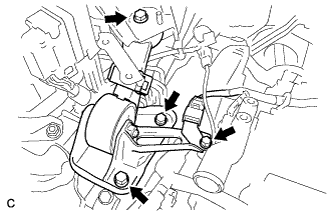 |
Remove the 4 bolts, the engine moving control rod and the bracket.
| 23. REMOVE NO. 2 ENGINE MOUNTING STAY RH |
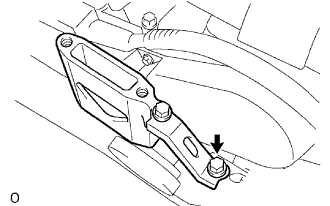 |
Remove the bolt, the No. 2 engine mounting stay and the No. 2 engine mounting bracket.
| 24. REMOVE IGNITION COIL ASSEMBLY |
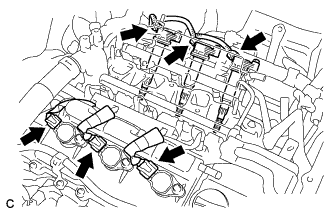 |
Disconnect the 6 ignition coil connectors.
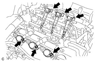 |
Remove the 6 bolts and 6 ignition coils.
| 25. REMOVE CYLINDER HEAD COVER SUB-ASSEMBLY |
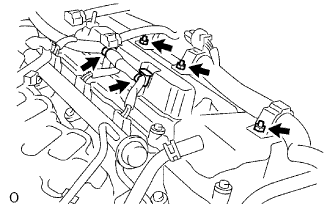 |
Remove the 2 engine wire harness clamps.
Remove the 3 nuts and disconnect the engine wire harness.
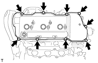 |
Remove the 9 bolts and the cylinder head cover.
| 26. REMOVE CRANKSHAFT PULLEY |
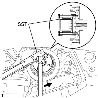 |
Using SST, loosen the pulley bolt.
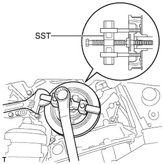 |
Using SST and the pulley bolt, remove the pulley.
| 27. REMOVE NO. 1 TIMING BELT COVER |
Remove the 4 bolts and the No. 1 timing belt cover.
| 28. REMOVE NO. 2 TIMING BELT COVER |
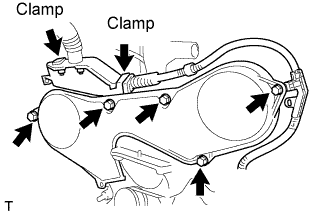 |
Disconnect the engine wire protector clamps from the No. 2 timing belt cover.
Remove the 5 bolts and the timing belt cover.
| 29. REMOVE ENGINE MOUNTING BRACKET RH |
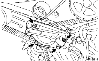 |
Remove the 2 bolts, 2 nuts and engine mounting bracket RH.
| 30. REMOVE NO. 2 TIMING BELT GUIDE |
| 31. REMOVE TIMING BELT |
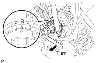 |
Set No. 1 cylinder to TDC/compression.
Temporarily install the crankshaft pulley bolt and washer to the crankshaft.
Turn the crankshaft clockwise, and align the timing mark of the crankshaft timing pulley with the oil pump body.
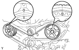 |
Check that the timing marks of the camshaft timing pulleys and No. 3 timing belt cover are aligned.
If not, turn the crankshaft 1 revolution (360°).
Remove the crankshaft pulley bolt.
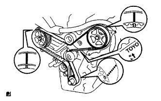 |
If reusing the timing belt, check that there are 4 installation marks on the timing belt as shown in the illustration.
If the installation marks have disappeared, put new installation marks on the timing belt before removing.
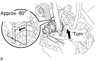 |
Set No. 1 cylinder to approximately 60° BTDC/compression.
Turn the crankshaft counterclockwise by approximately 60°.
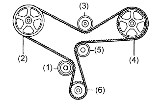 |
Remove the 2 bolts and No. 1 chain tensioner.
Remove the timing belt in the following order.
| 1st | No. 1 idler pulley |
| 2nd | RH camshaft timing pulley |
| 3rd | No. 2 idler pulley |
| 4th | LH camshaft timing pulley |
| 5th | Water pump pulley |
| 6th | Crankshaft timing pulley |
| 32. REMOVE NO. 2 TIMING BELT IDLER SUB-ASSEMBLY |
Remove the bolt and No. 2 timing belt idler sub-assembly.
| 33. REMOVE CAMSHAFT TIMING PULLEY |
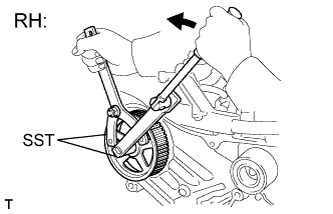 |
Using SST, remove the bolt and the RH timing pulley.
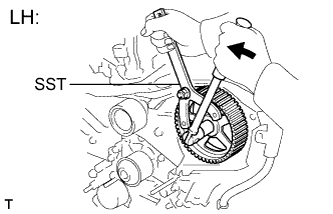 |
Using SST, remove the bolt and the LH timing pulley.
| 34. REMOVE NO. 3 TIMING BELT COVER |
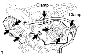 |
Disconnect the 2 engine wire harness clamps from the No. 3 timing belt cover.
Remove the 6 bolts and the timing belt cover.
| 35. REMOVE CAMSHAFT |
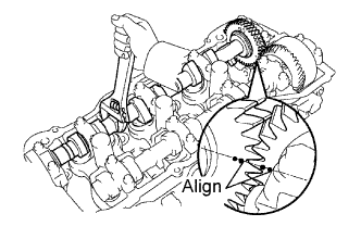 |
Align the timing marks (2-dot mark) of the camshaft drive and the driven gears by turning the camshaft with a wrench.
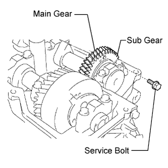 |
Secure the exhaust camshaft sub-gear to the main gear with a service bolt.
| Thread diameter | 6.0 mm (0.24 in.) |
| Thread pitch | 1.0 mm (0.04 in.) |
| Bolt length | 16 to 20 mm (0.63 to 0.79 in.) |
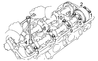 |
Using several steps, loosen and remove the 10 bearing cap bolts uniformly in the sequence shown in the illustration. Remove the 5 bearing caps and the camshaft.
| 36. REMOVE NO. 2 CAMSHAFT |
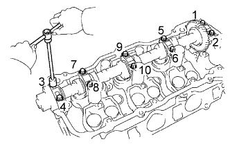 |
Using several steps, loosen and remove the 10 bearing cap bolts uniformly in the sequence shown in the illustration. Remove the 5 bearing caps and the No. 2 camshaft.
Remove the oil seal from the No. 2 camshaft.
| 37. INSPECT CAMSHAFT TIMING GEAR ASSEMBLY |
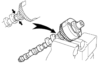 |
Clamp the camshaft in a vise on the hexagonal lobe.
Check that the VVT-i does not turn.
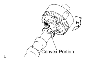 |
Cover all the oil ports with vinyl tape except the port on the advance angle side (nearest to the convex portion) shown in the illustration.
Apply about 100 kPa (1 kgf/cm2, 14 psi) of air pressure to the port on the advance angle side.
Turn the VVT-i to the advance angle side (the white arrow marked direction in the illustration) by hand.
Check that the VVT-i moves freely within about 30° range. Do not move the VVT-i unit to the most retard angle position as the lock-pin will be engaged again.
Turn the VVT-i by hand and lock it at the most retard angle position.
| 38. REMOVE CAMSHAFT TIMING GEAR ASSEMBLY |
|
Clamp the camshaft in a vise on the hexagonal lobe.
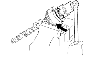 |
Using a 46 mm socket wrench, remove the lock nut by turning it clockwise.
Remove the camshaft timing gear assembly.
| 39. REMOVE CAMSHAFT SUB GEAR |
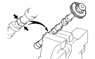 |
Clamp the camshaft in a vise on the hexagonal lobe.
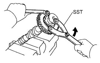 |
Using SST, turn the sub-gear counterclockwise, and remove the service bolt.
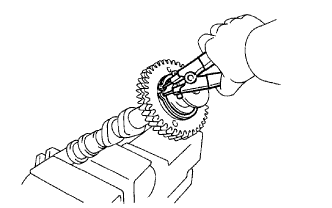 |
Using snap ring pliers, remove the snap ring.
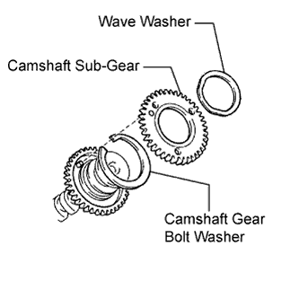 |
Remove the wave washer, camshaft sub-gear and camshaft gear bolt washer.