 |
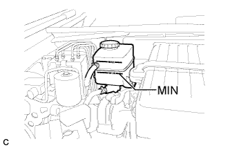
Drain the brake fluid in the reservoir tank near the MIN line.
BRAKE MASTER CYLINDER > REMOVAL |
| 1. PERFORM ACCUMULATOR ZERO DOWN |
|
Drain the brake fluid in the reservoir tank near the MIN line.
Connect the Techstream to the DLC3 with the power switch off.
Check that the parking brake is set, and turn the power switch on (IG).
Enter the following menus: Chassis / ABS/VSC/TRC / Utility / Electronically Controlled Brake system Utility / Zero Down.
When the buzzer sounds, turn the power switch off.
| 2. DRAIN BRAKE FLUID |
| 3. DISCONNECT CABLE FROM NEGATIVE BATTERY TERMINAL |
| 4. REMOVE SERVICE PLUG GRIP |
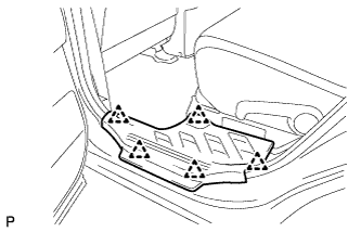 |
Remove the 5 clips and door scuff plate LH.
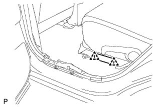 |
Remove the 2 clips and reclining hinge cover.
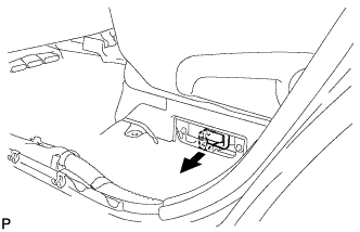 |
Wear insulated glove and remove the service plug grip, after sliding up the lever of the service plug grip.
| 5. DISCONNECT BRAKE BOOSTER PUMP CONNECTOR |
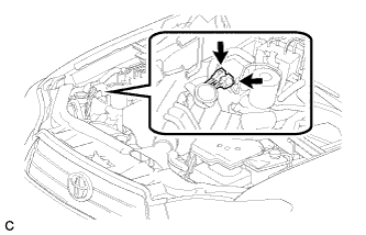 |
Disconnect or connect the 2 brake booster pump connectors as shown in the illustration.
| 6. REMOVE FRONT WIPER ARM AND BLADE ASSEMBLY LH |
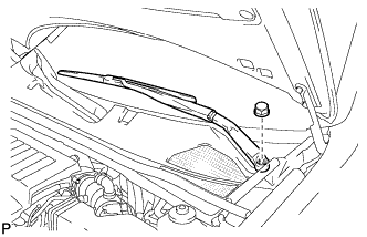 |
Remove the nut, and the front wiper arm and blade assembly LH.
| 7. REMOVE FRONT WIPER ARM AND BLADE ASSEMBLY RH |
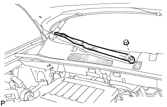 |
Remove the nut, and the front wiper arm and blade assembly RH.
| 8. REMOVE COWL TOP VENTILATOR LOUVER SUB-ASSEMBLY |
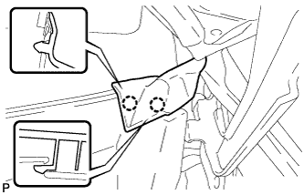 |
Disengage the 2 claws and disconnect the front fender to cowl side seal LH.
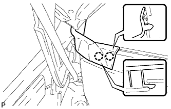 |
Disengage the 2 claws and disconnect the front fender to cowl side seal RH.
Remove the 2 clips.
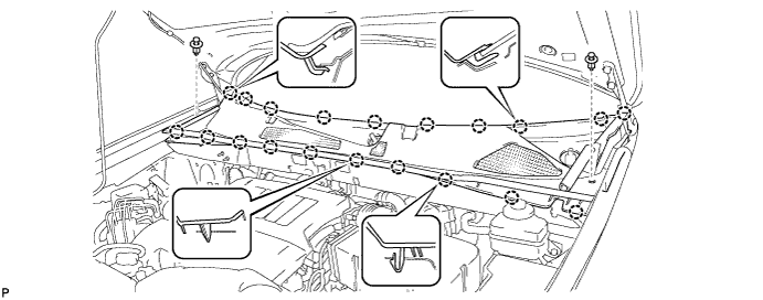
Disengage the 20 claws and remove the cowl top ventilator louver sub-assembly.
| 9. REMOVE WINDSHIELD WIPER MOTOR AND LINK |
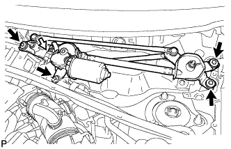 |
Disconnect the connector.
Remove the 4 bolts, and the windshield wiper motor and link assembly.
| 10. REMOVE OUTER COWL TOP PANEL SUB-ASSEMBLY |
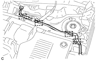 |
Disengage the 4 clamps and separate the wiper wire harness from the outer cowl top panel sub-assembly.
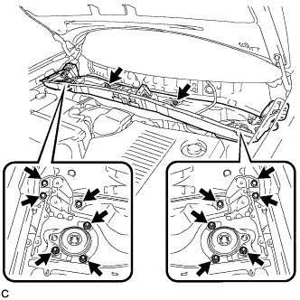 |
Remove the 8 bolts, 6 nuts, and the outer cowl top panel sub-assembly.
| 11. SEPARATE WIRE HARNESS |
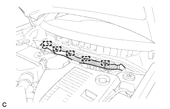 |
Disengage the 5 clamps and separate the wire harness from the body.
| 12. DISCONNECT NO. 1 RESERVOIR HOSE |
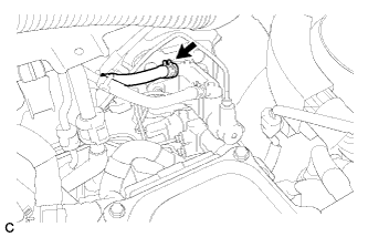 |
Slide the clip and disconnect the No. 1 reservoir hose from the brake master cylinder sub-assembly.
| 13. DISCONNECT NO. 2 RESERVOIR HOSE |
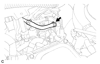 |
Slide the clip and disconnect the No. 2 reservoir hose from the brake master cylinder sub-assembly.
| 14. REMOVE BRAKE PEDAL RETURN SPRING |
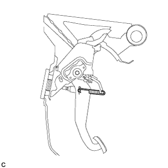 |
Remove the brake pedal return spring from the push rod pin and instrument panel reinforcement.
| 15. REMOVE PUSH ROD PIN |
Remove the clip and push rod pin, and separate the brake master cylinder push rod clevis from the brake pedal sub-assembly.
| 16. REMOVE BRAKE MASTER CYLINDER SUB-ASSEMBLY |
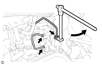 |
Using a union nut wrench (10 mm), disconnect the brake lines and remove the brake stroke simulator tube from the brake master cylinder sub-assembly.
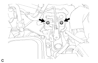 |
Remove the 2 nuts and brake master cylinder sub-assembly.
| 17. REMOVE BRAKE MASTER CYLINDER GASKET |
Remove the brake master cylinder gasket from the brake master cylinder sub-assembly.
| 18. REMOVE BRAKE STROKE SIMULATOR CYLINDER SUB-ASSEMBLY |
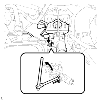 |
Using a union nut wrench (10 mm), disconnect the brake line from the brake stroke simulator cylinder sub-assembly.
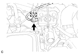 |
Disengage the clamp and disconnect the connector.
Remove the brake stroke simulator cylinder sub-assembly.
| 19. REMOVE BRAKE MASTER CYLINDER GASKET |
Remove the brake master cylinder gasket from the brake master cylinder bracket.
| 20. REMOVE BRAKE MASTER CYLINDER BRACKET |
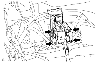 |
Remove the 4 nuts and brake master cylinder bracket.
| 21. REMOVE BRAKE BOOSTER GASKET |
Remove the brake booster gasket from the brake stroke simulator cylinder sub-assembly.