Home › BRAKE › BRAKE CONTROL › SKID CONTROL ECU

SKID CONTROL ECU > REMOVAL

for Preparation Click here


NOTICE:
While the battery is connected, even if the power switch is off, the brake control system activates when the brake pedal is depressed or any door courtesy switch turns on. Therefore, when servicing the brake system components, do not operate the brake pedal or open/close the doors while the battery is connected.


1. DISCONNECT CABLE FROM NEGATIVE BATTERY TERMINAL

CAUTION:
Wait at least 90 seconds after disconnecting the cable from the negative (-) battery terminal to prevent airbag and seat belt pretensioner activation.

NOTICE:
When disconnecting the cable, some systems need to be initialized after the cable is reconnected (Click here).


2. REMOVE SERVICE PLUG GRIP

CAUTION:
  1. Remove the service plug to interrupt a high voltage circuit at the time of the check.
  2. Keep the removed service plug in your pocket to prevent other technicians from accidentally reconnecting it while you are servicing the vehicle.
  3. All the high voltage wiring connectors are colored in orange.


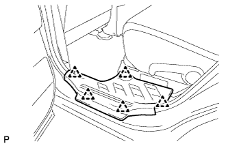
    A175634
  1. Remove the 5 clips and door scuff plate LH.
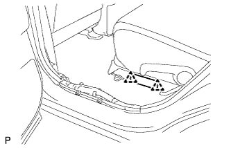


    A175635
  1. Remove the 2 clips and reclining hinge cover.


    A175636
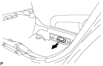
  1. Wear insulated glove and remove the service plug grip, after sliding up the lever of the service plug grip.

    CAUTION:
    1. Keep the removed service plug in your pocket to prevent other technicians from accidentally reconnecting it while you are servicing the vehicle.
    2. After removing the service plug grip, do not touch the high voltage connectors and terminals for 5 minutes.

    NOTICE:
    After removing the service plug grip, do not operate the power switch as it may damage the hybrid vehicle control ECU.


3. REMOVE FRONT DOOR SCUFF PLATE RH

HINT:
Use the same procedure for the RH side and the LH side.


4. REMOVE COWL SIDE TRIM SUB-ASSEMBLY RH

HINT:
Use the same procedure for the RH side and the LH side.


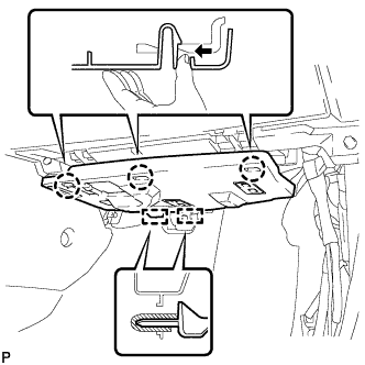
5. REMOVE NO. 2 INSTRUMENT PANEL UNDER COVER SUB-ASSEMBLY


    B172999
  1. Disengage the 3 claws.

  1. Disengage the 2 guides and remove the No. 2 instrument panel under cover sub-assembly.


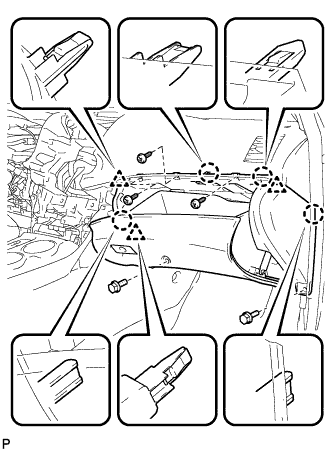
6. REMOVE LOWER INSTRUMENT PANEL SUBASSEMBLY


    B168370
  1. Remove the 2 bolts <B> and 3 screws <E>.

  1. Disengage the 4 claws and 3 clips.

  1. Disconnect each connector and clamp, and remove the lower instrument panel sub-assembly.


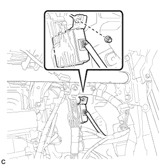
7. REMOVE TIRE PRESSURE MONITOR ECU


    C165671
  1. Remove the nut.


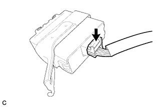
    C165672
  1. Disconnect the connector and remove the tire pressure warning ECU.


8. DISCONNECT WIRE HARNESS


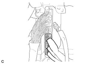
    C171432
  1. Disconnect the 3 connectors from the hybrid vehicle control ECU.


9. REMOVE SKID CONTROL ECU


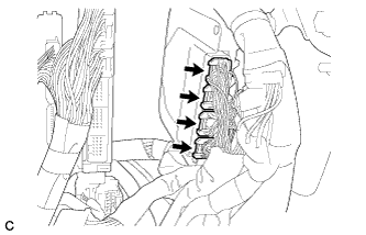
    C171431
  1. Disconnect the 4 connectors from the skid control ECU.


    C171433
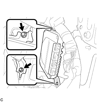
  1. Remove the 2 bolts and skid control ECU.