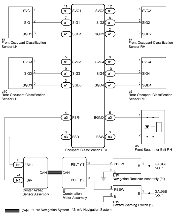
SEAT BELT WARNING SYSTEM > Front Passenger Side Seat Belt Warning Light Malfunction |
| 1.CHECK FOR DTCs |
Check for DTCs.
| Result | Proceed to |
| No output DTC | A |
| Output DTC (CAN communication) | B |
| Output DTC (Occupant detection) | C |
|
| ||||
|
| ||||
| A | |
 |
| 2.PERFORM ACTIVE TEST USING TECHSTREAM |
Connect Techstream to the DLC3.
Turn the power switch on (IG).
Read the DATA LIST according to the displays on the tester screen.
| Tester Display | Test Part | Control Range | Diagnostic Note |
| Front Passenger Side Seat Belt | Front passenger side seat belt warning light | Front passenger side seat belt warning light is OFF / ON | Confirm that the vehicle is stopped, engine idling |
|
| ||||
| OK | ||
 | ||
| ||
| 3.CHECK WIRE HARNESS (BATTERY POSITIVE AND BODY GROUND) |
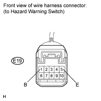 |
Disconnect the E19 connector.
Measure the voltage and resistance according to the value(s) in the table below.
| Tester Connection | Condition | Specified Condition |
| E19-1 (B) - Body ground | Power switch on (IG) | 11 to 14 V |
| Tester Connection | Condition | Specified Condition |
| E19-5 (E) - Body ground | Always | Below 1 Ω |
|
| ||||
| OK | |
|
| 4.CHECK HARNESS OR CONNECTOR |
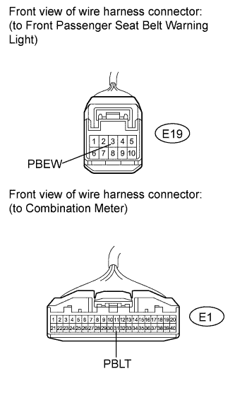 |
Disconnect the E1 connector.
Measure the resistance according to the value(s) in the table below.
| Tester Connection | Condition | Specified Condition |
| E1-31 (PBLT) - E19-3 (PBEW) | Always | Below 1 Ω |
| E1-31 (PBLT) or E19-3 (PBEW) - Body ground | Always | 10 kΩ or higher |
Proceed to the next step based on the inspection result.
| Result | Proceed to |
| NG | A |
| OK (w/ Navigation System) | B |
| OK (w/o Navigation System) | C |
|
| ||||
|
| ||||
| C | ||
| ||
| ||

