 |
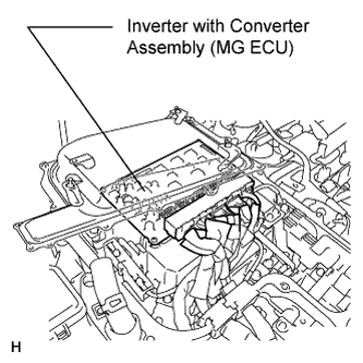
Check the connections of the MG ECU connectors.
- OK:
- The connectors are connected securely and there are no contact problems.
DTC P0A69-677 Drive Motor "B" Phase V Current |
DTC P0A69-679 Drive Motor "B" Phase V Current |
DTC P0A69-680 Drive Motor "B" Phase V Current |
DTC P0A69-683 Drive Motor "B" Phase V Current |
DTC P0A69-684 Drive Motor "B" Phase V Current |
DTC P0A69-688 Drive Motor "B" Phase V Current |
DTC P0A6C-678 Drive Motor "B" Phase W Current |
DTC P0A6C-681 Drive Motor "B" Phase W Current |
DTC P0A6C-682 Drive Motor "B" Phase W Current |
DTC P0A6C-685 Drive Motor "B" Phase W Current |
DTC P0A6C-686 Drive Motor "B" Phase W Current |
DTC P0A6C-689 Drive Motor "B" Phase W Current |
| DTC No. | INF Code | DTC Detection Condition | Trouble Area |
| P0A69 | 677 | Performance problem of the rear motor inverter current sensor phase V |
|
| 679 | Open in the rear motor inverter current sensor (phase V main sensor) circuit | ||
| 680 | Open in the rear motor inverter current sensor (phase V sub sensor) circuit | ||
| 683 | Malfunction in the rear motor inverter current sensor (phase V main sensor) | ||
| 684 | Malfunction in the rear motor inverter current sensor (phase V sub sensor) | ||
| 688 | Malfunction in the rear motor inverter current sensor (phase V main and sub sensors offset) | ||
| P0A6C | 678 | Performance problem of the rear motor inverter current sensor phase W | |
| 681 | Open in the rear motor inverter current sensor (phase W main sensor) circuit | ||
| 682 | Open in the rear motor inverter current sensor (phase W sub sensor) circuit | ||
| 685 | Malfunction in the rear motor inverter current sensor (phase W main sensor) | ||
| 686 | Malfunction in the rear motor inverter current sensor (phase W sub sensor) | ||
| 689 | Malfunction in the rear motor inverter current sensor (phase W main and sub sensors offset) |
| Related DTCs | P0A69 (INF 677): Rear motor inverter current sensor / Phase V deviation / Short to GND P0A69 (INF 679): Rear motor inverter current sensor / Phase V, main sensor / Open circuit P0A69 (INF 680): Rear motor inverter current sensor / Phase V, sub sensor / Open circuit P0A69 (INF 683): Rear motor inverter current sensor / Phase V, main sensor / Out of range P0A69 (INF 684): Rear motor inverter current sensor / Phase V, sub sensor / Out of range P0A69 (INF 688): Rear motor inverter current sensor / Offset malfunction P0A6C (INF 678): Rear motor inverter current sensor / Phase W deviation / Short to GND P0A6C (INF 681): Rear motor inverter current sensor / Phase W, main sensor / Open circuit P0A6C (INF 682): Rear motor inverter current sensor / Phase W, sub sensor / Open circuit P0A6C (INF 685): Rear motor inverter current sensor / Phase W, main sensor / Out of range P0A6C (INF 686): Rear motor inverter current sensor / Phase W, sub sensor / Out of range P0A6C (INF 689): Rear motor inverter current sensor / Offset malfunction |
| Required sensors / components | Rear motor inverter current sensor, motor resolver |
| Frequency of operation | Continuous |
| Duration | TMC's intellectual property |
| MIL operation | Immediately |
| Sequence of operation | None |
| The monitor will run whenever the DTCs listed are not present | TMC's intellectual property |
| Other conditions belong to TMC's intellectual property | - |
| TMC's intellectual property | - |
| Rear motor inverter current sensor | DTC P0A69 (INF 677/679/680/683/684/688) is not detected |
| Rear motor inverter current sensor | DTC P0A6C (INF 678/681/682/685/686/689) is not detected |
| 1.CHECK CONNECTOR CONNECTION CONDITION (MG ECU CONNECTOR) |
Turn the power switch off.
Remove the service plug grip (Click here).
Remove the inverter cover (Click here).
|
Check the connections of the MG ECU connectors.
|
| ||||
| OK | ||
 | ||
| ||
