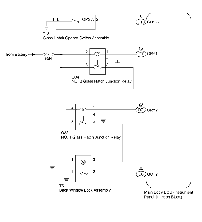
GLASS HATCH OPENER SYSTEM > Glass Hatch Opener System does not Operate |
| 1.SYSTEM CHECK |
Confirm that the vehicle is equipped with the smart key system.
| Result | Proceed to |
| w/ Smart Key System | A |
| w/o Smart Key System | B |
|
| ||||
| A | |
 |
| 2.CHECK SMART KEY SYSTEM |
When the back door entry lock switch is operated, check that the back door locks.
|
| ||||
| OK | |
|
| 3.PERFORM ACTIVE TEST BY TECHSTREAM |
Connect the Techstream to the DLC3.
Turn the power switch on (IG).
Turn the Techstream on.
Select the item below in the Active Test and then check that the relay operates.
| Tester Display | Test Part | Control Range | Diagnostic Note |
| Glass Hatch Open | Operate Glass Hatch | ON or OFF | - |
|
| ||||
| OK | |
|
| 4.READ VALUE ON TECHSTREAM (GLASS HATCH COURTESY SWITCH) |
Connect the Techstream to the DLC3.
Turn the power switch on (IG).
Turn the Techstream on.
Select the items below in the Data List, and read the displays on the Techstream.
| Tester Display | Measurement Item/Range | Normal Condition | Diagnostic Note |
| Glass Hatch Courtesy Switch | Glass hatch courtesy switch signal / ON or OFF | ON: Glass hatch is open OFF: Glass hatch is closed | - |
|
| ||||
| OK | |
|
| 5.READ VALUE ON TECHSTREAM (GLASS HATCH OPENER SWITCH) |
Connect the Techstream to the DLC3.
Turn the power switch on (IG).
Turn the Techstream on.
Select the items below in the Data List, and read the displays on the Techstream.
| Tester Display | Measurement Item/Range | Normal Condition | Diagnostic Note |
| Glass Hatch Opener Switch | Glass hatch opener switch signal / ON or OFF | ON: Glass hatch opener switch Operates OFF: Glass hatch opener switch does not Operate | - |
|
| ||||
| OK | ||
 | ||
| ||
| 6.INSPECT BACK WINDOW LOCK ASSEMBLY |
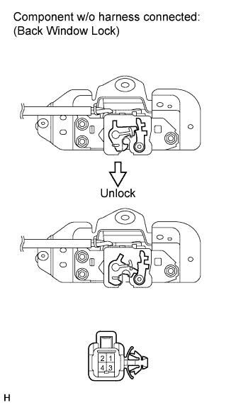 |
Measure the resistance according to the value(s) in the table below.
| Tester Connection | Condition | Specified Condition |
| 1 - 2 | Voltage is not applied between terminals 3 and 4 | 10 kΩ or higher |
| 1 - 2 | Apply battery voltage between terminals 3 and 4 | Below 1 Ω |
|
| ||||
| OK | |
|
| 7.INSPECT GLASS HATCH OPENER SWITCH ASSEMBLY |
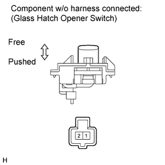 |
Measure the resistance according to the value(s) in the table below.
| Tester Connection | Condition | Specified Condition |
| 1 - 2 | Switch free | 10 kΩ or higher |
| 1 - 2 | Switch pushed | Below 1 Ω |
|
| ||||
| OK | |
|
| 8.CHECK NO. 2 GLASS HATCH JUNCTION RELAY |
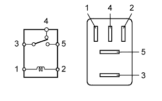 |
Measure the resistance according to the value(s) in the table below.
| Tester Connection | Condition | Specified Condition |
| 3 - 4 | Voltage is not applied between terminals 1 and 2 | Below 1 Ω |
| 3 - 4 | Apply battery voltage between terminals 1 and 2 | 10 kΩ or higher |
| 3 - 5 | Voltage is not applied between terminals 1 and 2 | 10 kΩ or higher |
| 3 - 5 | Apply battery voltage between terminals 1 and 2 | Below 1 Ω |
|
| ||||
| OK | |
|
| 9.CHECK NO. 1 GLASS HATCH JUNCTION RELAY |
|
Measure the resistance according to the value(s) in the table below.
| Tester Connection | Condition | Specified Condition |
| 3 - 4 | Voltage is not applied between terminals 1 and 2 | Below 1 Ω |
| 3 - 4 | Apply battery voltage between terminals 1 and 2 | 10 kΩ or higher |
| 3 - 5 | Voltage is not applied between terminals 1 and 2 | 10 kΩ or higher |
| 3 - 5 | Apply battery voltage between terminals 1 and 2 | Below 1 Ω |
|
| ||||
| OK | |
|
| 10.CHECK HARNESS AND CONNECTOR (MAIN BODY ECU - Glass Hatch Opener Switch) |
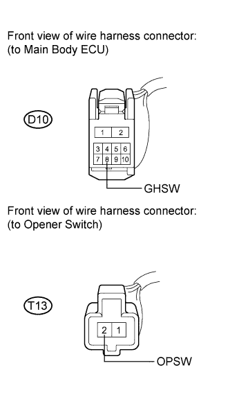 |
Disconnect the D10 and T13 connectors.
Measure the resistance according to the value(s) in the table below.
| Tester Connection | Condition | Specified Condition |
| D10-8 (GHSW) - T13-2 (OPSW) | Always | Below 1 Ω |
| D10-8 (GHSW) or T13-2 (OPSW) - Body ground | Always | 10 kΩ or higher |
|
| ||||
| OK | |
|
| 11.CHECK HARNESS AND CONNECTOR (MAIN BODY ECU - NO. 2 JUNCTION RELAY) |
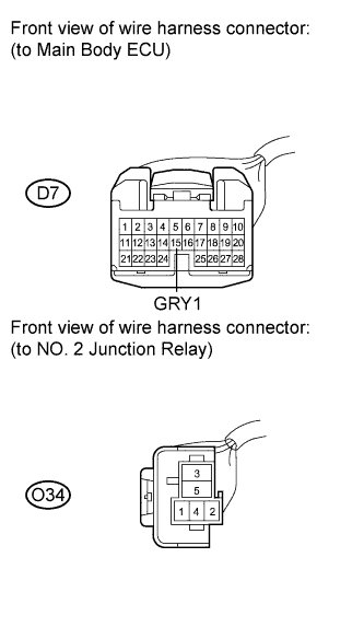 |
Disconnect the D7 and O34 connectors.
Measure the resistance according to the value(s) in the table below.
| Tester Connection | Condition | Specified Condition |
| D7-15 (GRY1 ) - O34-1 | Always | Below 1 Ω |
| D7-15 (GRY1 ) or O34-1 - Body ground | Always | 10 kΩ or higher |
|
| ||||
| OK | |
|
| 12.CHECK HARNESS AND CONNECTOR (NO.2 JUNCTION RELAY - NO. 1 JUNCTION RELAY) |
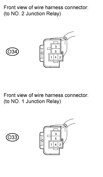 |
Disconnect the O34 and O33 connectors.
Measure the resistance according to the value(s) in the table below.
| Tester Connection | Condition | Specified Condition |
| O34-3 - O33-2 | Always | Below 1 Ω |
| O34-3 or O33-2 - Body ground | Always | 10 kΩ or higher |
|
| ||||
| OK | |
|
| 13.CHECK HARNESS AND CONNECTOR (NO. 1 JUNCTION RELAY - MAIN BODY ECU) |
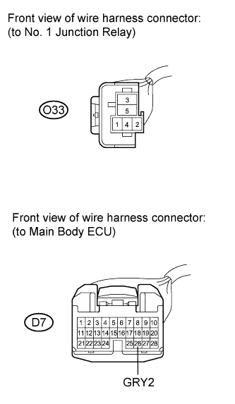 |
Disconnect the O33 and D7 connectors.
Measure the resistance according to the value(s) in the table below.
| Tester Connection | Condition | Specified Condition |
| O33-1 - D7-26 (GRY2) | Always | Below 1 Ω |
| O33-1 or D7-26 (GRY2) - Body ground | Always | 10 kΩ or higher |
|
| ||||
| OK | |
|
| 14.CHECK HARNESS AND CONNECTOR (NO. 1 JUNCTION RELAY - BACK WINDOW LOCK ASSEMBLY)) |
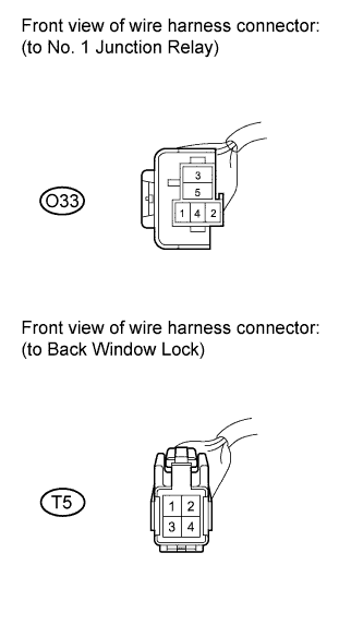 |
Disconnect the O33 and T5 connectors.
Measure the resistance according to the value(s) in the table below.
| Tester Connection | Condition | Specified Condition |
| O33-3 - T5-3 | Always | Below 1 Ω |
| O33-3 or T5-3 - Body ground | Always | 10 kΩ or higher |
|
| ||||
| OK | |
|
| 15.CHECK HARNESS AND CONNECTOR (MAIN BODY ECU - BACK WINDOW LOCK ASSEMBLY)) |
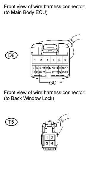 |
Disconnect the D8 and T5 connectors.
Measure the resistance according to the value(s) in the table below.
| Tester Connection | Condition | Specified Condition |
| D8-20 (GCTY) - T5-2 | Always | Below 1 Ω |
| D8-20 (GCTY) or T5-2 - Body ground | Always | 10 kΩ or higher |
|
| ||||
| OK | ||
| ||
| ||

