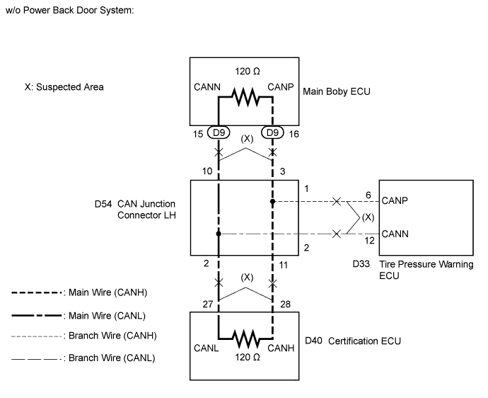
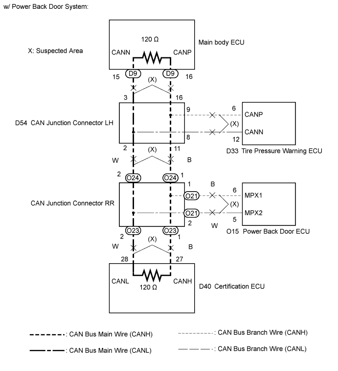
DTC U1002 (CAN MS BUS) Lost Communication with Gateway Module (Main body ECU) |
| DTC No. | DTC Detection Condition | Trouble Area |
| U1002 | Main body ECU cannot receive signals from all ECUs that have been memorized as those connected to the CAN MS bus. |
|
| 1.CHECK CAN MS BUS WIRE |
Turn the power switch off.
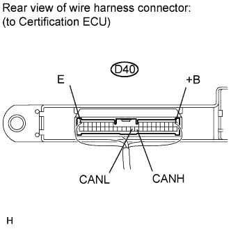 |
Measure the resistance according to the value(s) in the table below.
| Tester Connection | Switch Condition | Specified Condition | Result |
| D40-27 (CANH) - D40-28 (CANL) | Power switch off | 54 to 69 Ω | Below 53 Ω: Short in lines |
| 70 Ω or more: Open in CAN bus main wire | |||
| D40-27 (CANH) - D40-17 (E) | Power switch off | 200 Ω or higher | Below 200 Ω: Ground short |
| D40-28 (CANL) - D40-17 (E) | |||
| D40-27 (CANH) - D40-1 (+B) | Negative battery terminal disconnected | 6 kΩ or higher | Below 6 kΩ: +B short |
| D40-28 (CANL) - D40-1 (+B) |
| Result | Proceed to |
| OK | A |
| Open in CAN main wire | B |
| Short in lines, Ground short, +B short | C |
|
| ||||
|
| ||||
| A | ||
 | ||
| ||
| 2.CHECK FOR OPEN IN CAN MS BUS MAIN WIRE (CAN JUNCTION CONNECTOR LH) |
Disconnect the CAN junction connector LH.
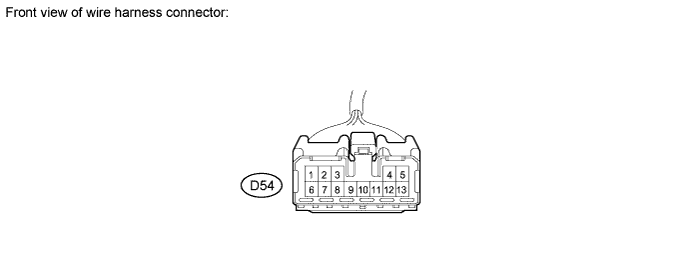
Measure the resistance according to the value(s) in the table below.
| Tester Connection | Connect to | Switch Condition | Specified Condition |
| D54-10 (CANH) - D54-3 (CANL) | Main body ECU | Power switch off | 108 to 132 Ω |
| D54-11 (CANH) - D54-2 (CANL) |
| Power switch off | 108 to 132 Ω |
| Result | Proceed to |
| OK | A |
| NG (Main body ECU wire) | B |
| NG (Certification ECU wire) | C |
| NG (CAN junction connector RR wire) | D |
|
| ||||
|
| ||||
|
| ||||
| A | ||
| ||
| ||
| 3.CHECK FOR OPEN IN CAN MS BUS MAIN WIRE (MAIN BODY ECU) |
Reconnect the CAN junction connector LH.
Disconnect the main body ECU connector (D9) from the main body ECU.
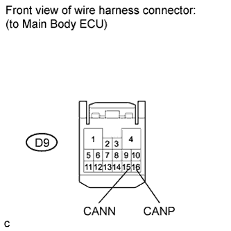 |
Measure the resistance according to the value(s) in the table below.
| Tester Connection | Switch Condition | Specified Condition |
| D9-16 (CANP) - D9-15 (CANN) | Power switch off | 108 to 132 Ω |
|
| ||||
| OK | ||
| ||
| ||
| 4.CHECK FOR OPEN IN CAN MS BUS MAIN WIRE (CERTIFICATION ECU) |
Reconnect the CAN junction connector LH.
Disconnect the certification ECU connector from the certification ECU.
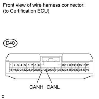 |
Measure the resistance according to the value(s) in the table below.
| Tester Connection | Switch Condition | Specified Condition |
| D40-27 (CANH) - D40-28 (CANL) | Power switch off | 108 to 132 Ω |
|
| ||||
| OK | ||
| ||
| ||
| 5.CHECK FOR OPEN IN CAN MS BUS MAIN WIRE (CAN JUNCTION CONNECTOR RR) |
Reconnect the CAN junction connector LH.
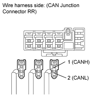 |
Disconnect the three connectors from the CAN junction connector RR.
| Connector Color | Connect to |
| Black | Back door ECU |
| Natural Color | Certification ECU |
| Gray | CAN junction connector LH |
Measure the resistance according to the value(s) in the table below.
| Tester Connection [Connector Color] | Switch Condition | Specified Condition |
| Black-1 (CANH) - Black-2 (CANL) | Power switch off | 1M Ω or higher |
| Natural-1 (CANH) - Natural-2(CANL) | Power switch off | 108 to 132 Ω |
| Gray-1 (CANH) - Gray-2 (CANL) | Power switch off | 108 to 132 Ω |
| Result | Proceed to |
| Gray and natural color connectors are 108 to 132 Ω (Wire harness are normal) | A |
| Natural color connector is only 108 to 132 Ω (Certification ECU wire is normal) | B |
| Gray connector is only 108 to 132 Ω (CAN junction connector LH wire is normal) | C |
|
| ||||
|
| ||||
| A | ||
| ||
| ||
| 6.CHECK FOR OPEN IN CAN MS BUS MAIN WIRE (CERTIFICATION ECU) |
Reconnect the CAN junction connector LH and CAN junction connector RR.
Disconnect the certification ECU connector from the certification ECU.
|
Measure the resistance according to the value(s) in the table below.
| Tester Connection | Switch Condition | Specified Condition |
| D40-27 (CANH) - D40-28 (CANL) | Power switch off | 108 to 132 Ω |
|
| ||||
| OK | ||
| ||
| ||
| 7.CHECK FOR SHORT IN CAN MS BUS WIRES (CAN JUNCTION CONNECTOR LH) |
Disconnect the CAN junction connector LH.
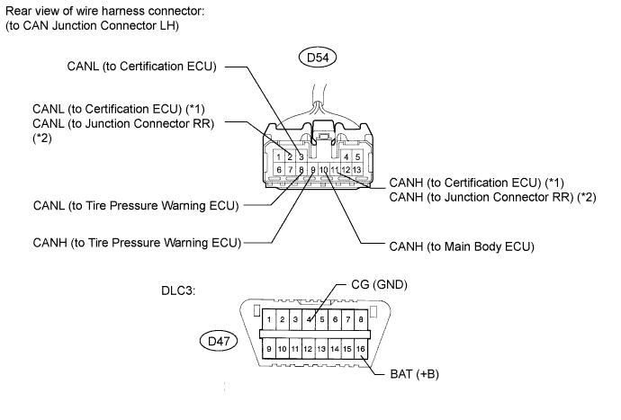
Measure the resistance according to the value(s) in the table below.
| Tester Connection | Connect to | Condition | Specified Condition |
| D54-10 (CANH) | Main body ECU | Power switch off | CANH - CANL: 108 to 132 Ω CANH, CANL - GND: 200 Ω or higher |
| D54-3 (CANL) | Negative battery terminal disconnected | CANH, CANL - +B: 6k Ω or higher | |
| D54-11 (CANH) |
| Power switch off | CANH - CANL: 108 to 132 Ω CANH, CANL - GND: 200 Ω or higher |
| D54-2 (CANL) | Negative battery terminal disconnected | CANH, CANL - +B: 6k Ω or higher | |
| D54-9 (CANH) | Tire pressure warning ECU | Power switch off | CANH - CANL: 1M Ω or higher CANH, CANL - GND: 200 Ω or higher |
| D54-8 (CANL) | Negative battery terminal disconnected | CANH, CANL - +B: 6k Ω or higher |
| Result | Proceed to |
| OK | A |
| NG (Main body ECU wire) | B |
| NG (Certification ECU wire) | C |
| NG (Tire pressure warning ECU wire) | D |
| NG (CAN junction connector RR wire) | E |
|
| ||||
|
| ||||
|
| ||||
|
| ||||
| A | ||
| ||
| ||
| 8.CHECK FOR SHORT IN CAN MS BUS WIRES (MAIN BODY ECU) |
Disconnect the main body ECU connector (D9) from the main body ECU.
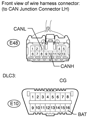 |
Measure the resistance according to the value(s) in the table below.
| Tester Connection | Condition | Specified Condition |
| D54-10 (CANH) - D54-3 (CANL) | Power switch off | 1 MΩ or higher |
| D54-10 (CANH) - D47-4 (CG) | Power switch off | 200 Ω or higher |
| D54-3 (CANL) - D47-4 (CG) | ||
| D54-10 (CANH) - D47-16 (BAT) | Negative battery terminal disconnected | 6 kΩ or higher |
| D54-3 (CANL) - D47-16 (+B) |
|
| ||||
| OK | ||
| ||
| ||
| 9.CHECK FOR SHORT IN CAN MS BUS WIRES (CERTIFICATION ECU) |
Disconnect the certification ECU connector from the certification ECU.
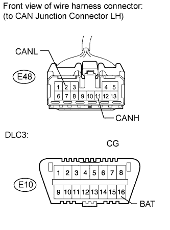 |
Measure the resistance according to the value(s) in the table below.
| Tester Connection | Condition | Specified Condition |
| D54-11 (CANH) - D54-2 (CANL) | Power switch off | 1 MΩ or higher |
| D54-11 (CANH) - D47-4 (CG) | Power switch off | 200 Ω or higher |
| D54-2 (CANL) - D47-4 (CG) | ||
| D54-11 (CANH) - D47-16 (BAT) | Negative battery terminal disconnected | 6 kΩ or higher |
| D54-2 (CANL)- D47-16 (+B) |
|
| ||||
| OK | ||
| ||
| ||
| 10.CHECK FOR SHORT IN CAN BUS MAIN WIRE (TIRE PRESSURE WARNING ECU) |
Disconnect the tire pressure warning ECU connector from the tire pressure warning ECU.
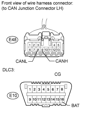 |
Measure the resistance according to the value(s) in the table below.
| Tester Connection | Condition | Specified Condition |
| D54-9 (CANH) - D54-8 (CANL) | Power switch off | 1 MΩ or higher |
| D54-9 (CANH) - D47-4 (CG) | Power switch off | 200 Ω or higher |
| D54-8 (CANL) - D47-4 (CG) | ||
| D54-9 (CANH) - D47-16 (BAT) | Negative battery terminal disconnected | 6 kΩ or higher |
| D54-8 (CANL)- D47-16 (+B) |
|
| ||||
| OK | ||
| ||
| ||
| 11.CHECK FOR SHORT IN CAN MS BUS WIRES (CAN JUNCTION CONNECTOR RR) |
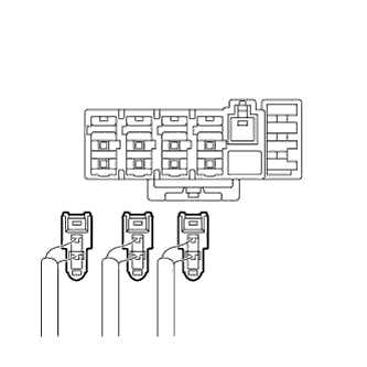 |
Disconnect the three connectors from the CAN junction connector RR.
| Connector Color | Connect to |
| Black | Back door ECU |
| Natural Color | Certification ECU |
| Gray | CAN junction connector LH |
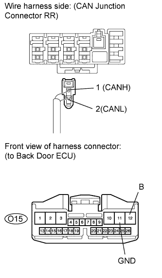 |
Check the three connectors for short.
| Tester Connection | Condition | Specified Condition |
| 1 (CANH) - 2 (CANL) | Power switch off | 108 Ω or higher |
| 1 (CANH) - O15-11 (GND) | Power switch off | 200 Ω or higher |
| 2 (CANL) - O15-11 (GND) | Power switch off | 200 Ω or higher |
| 1 (CANH) - O15-12 (B) | Negative battery terminal disconnected | 6 kΩ or higher |
| 2 (CANL) - O15-12 (B) | Negative battery terminal disconnected | 6 kΩ or higher |
| Result | Proceed to |
| OK | A |
| NG (Gray connector/ to CAN junction connector LH wire) | B |
| NG (Natural color connector/ to certification ECU wire) | C |
| NG (Block connector/ to back door ECU wire) | D |
|
| ||||
|
| ||||
|
| ||||
| A | ||
| ||
| ||
| 12.CHECK FOR SHORT IN CAN MS BUS WIRES (CAN JUNCTION CONNECTOR LH) |
|
Measure the resistance according to the value(s) in the table below.
| Tester Connection | Condition | Specified Condition |
| D54-11 (CANH) - D54-2 (CANL) | Power switch off | 1 MΩ or higher |
| D54-11 (CANH) - D47-4 (CG) | Power switch off | 200 Ω or higher |
| D54-2 (CANL) - D47-4 (CG) | ||
| D54-11 (CANH) - D47-16 (BAT) | Negative battery terminal disconnected | 6 kΩ or higher |
| D54-2 (CANL)- D47-16 (+B) |
|
| ||||
| OK | ||
| ||
| ||
| 13.CHECK FOR SHORT IN CAN MS BUS WIRES (CERTIFICATION ECU) |
Disconnect the certification ECU connector from the certification ECU.
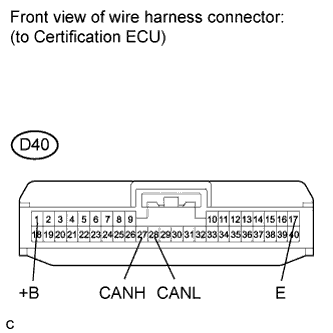 |
Measure the resistance according to the value(s) in the table below.
| Tester Connection | Condition | Specified Condition |
| D40-27 (CANH) - D40-28 (CANL) | Power switch off | 1M Ω or higher |
| D40-27 (CANH) - D40-17 (E) | Power switch off | 200 Ω or higher |
| D40-28 (CANL) - D40-17 (E) | ||
| D40-27 (CANH) - D40-1 (+B) | Negative battery terminal disconnected | 6 kΩ or higher |
| D40-28 (CANL) - D40-1 (+B) |
|
| ||||
| OK | ||
| ||
| ||
| 14.CHECK FOR SHORT IN CAN MS BUS WIRES (BACK DOOR ECU) |
Disconnect the back door ECU connector from the back door ECU.
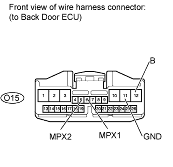 |
Measure the resistance according to the value(s) in the table below.
| Tester Connection | Condition | Specified Condition |
| O15-6 (MPX1) - O15-5 (MPX2) | Power switch off | 1 MΩ or higher |
| O15-6 (MPX1) - O15-11 (GND) | Power switch off | 200 Ω or higher |
| O15-5 (MPX2) - O15-11 (GND) | ||
| O15-6 (MPX1) - O15-12 (B) | Negative battery terminal disconnected | 6 kΩ or higher |
| O15-5 (MPX2) - O15-12 (B) |
|
| ||||
| OK | ||
| ||
| ||

