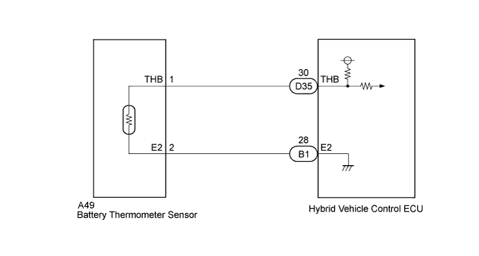
DTC P0516-769 Battery Temperature Sensor Circuit Low |
DTC P0517-770 Battery Temperature Sensor Circuit High |
| DTC No. | INF Code | DTC Detection Condition | Trouble Area |
| P0516 | 769 | GND short in battery thermometer sensor signal circuit |
|
| P0517 | 770 | Open or +B short in battery thermometer sensor signal circuit |
| 1.CHECK CONNECTOR CONNECTION CONDITION (HYBRID VEHICLE CONTROL ECU CONNECTOR) |
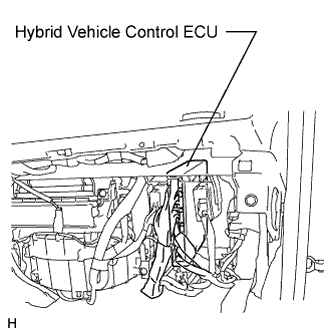 |
Check the connections of the hybrid vehicle control ECU connectors.
|
| ||||
| OK | |
 |
| 2.CHECK CONNECTOR CONNECTION CONDITION (BATTERY THERMOMETER SENSOR CONNECTOR) |
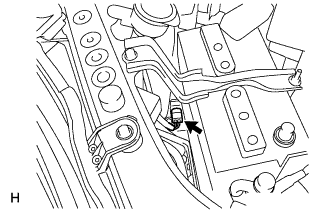 |
Check the connection of the battery thermometer sensor connector.
|
| ||||
| OK | |
|
| 3.CHECK BATTERY (BATTERY THERMOMETER SENSOR) |
Disconnect the battery thermometer sensor connector.
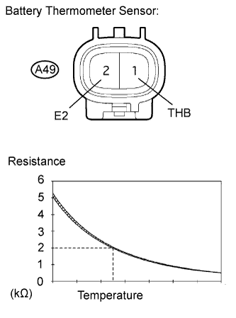 |
Measure the resistance according to the value(s) in the table below.
| Tester Connection | Condition | Specified Condition |
| A49-1 (THB) - A49-2 (E2) | 75.2 to 78.8°F (24 to 26°C) | 1.91 to 2.05 kΩ |
|
| ||||
| OK | |
|
| 4.CHECK HARNESS AND CONNECTOR (HYBRID VEHICLE CONTROL ECU - BATTERY THERMOMETER SENSOR) |
Disconnect connectors D35 and B1 from the hybrid vehicle control ECU.
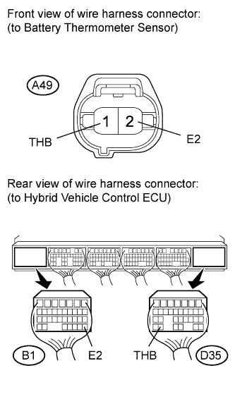 |
Measure the resistance according to the value(s) in the table below.
| Tester Connection | Switch Condition | Specified Condition |
| D35-30 (THB) - A49-1 (THB) | Power switch off | Below 1 Ω |
| B1-28 (E2) - A49-2 (E2) | Power switch off | Below 1 Ω |
| Tester Connection | Switch Condition | Specified Condition |
| D35-30 (THB) or A49-1 (THB) - Body ground and other terminals | Power switch off | 10 kΩ or higher |
| B1-28 (E2) or A49-2 (E2) - Body ground and other terminals | Power switch off | 10 kΩ or higher |
Turn the power switch on (IG).
Measure the voltage according to the value(s) in the table below.
| Tester Connection | Switch Condition | Specified Condition |
| D35-30 (THB) or A49-1 (THB) - Body ground | Power switch on (IG) | Below 1 V |
|
| ||||
| OK | ||
 | ||
| ||
