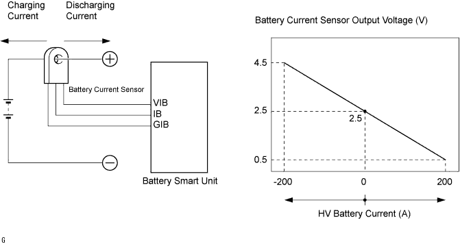
DTC P0AC0-817 Hybrid Battery Pack Current Sensor Circuit Range / Performance |
| DTC No. | INF Code | DTC Detection Condition | Trouble Area |
| P0AC0 | 817 | HV battery current sensor performance problem |
|
| Related DTCs | P0AC0 (INF 817): Current sensor malfunction (gain or offset) |
| Required sensors / components | Battery smart unit, battery current sensor |
| Frequency of operation | Continuous |
| Duration | TMC's intellectual property |
| MIL operation | 1 driving cycle |
| Sequence of operation | None |
| The monitor will run whenever the following DTCs are not present | TMC's intellectual property |
| Other conditions belong to TMC's intellectual property | - |
| TMC's intellectual property | - |
| Hybrid vehicle converter | DTC P0AC0 (INF 817) is not detected |
| 1.CHECK DTC OUTPUT (HV) |
Connect the Techstream to the DLC3.
Turn the power switch on (IG).
Select the following menu items: Powertrain / Hybrid Control / Trouble Codes.
Check if DTCs are output.
| Result | Proceed to |
| P0AC0-817 only is output. | A |
| P0A1F-123 is also output. | B |
|
| ||||
| A | |
 |
| 2.REPLACE HV RELAY ASSEMBLY |
Replace the HV relay assembly (Click here).
| NEXT | |
|
| 3.CLEAR DTC |
Select the following menu items: Powertrain / Hybrid Control / Trouble Codes.
Read and record the DTCs and freeze frame data.
Select the following menu items: Powertrain / Hybrid Control / Trouble Codes.
Clear DTCs and freeze frame data.
| NEXT | |
|
| 4.PERFORM ROAD TEST |
Perform a road test.
| NEXT | |
|
| 5.CHECK DTC OUTPUT (HV) |
Select the following menu items: Powertrain / Hybrid Control / Trouble Codes.
Check if DTCs are output.
| Result | Proceed to |
| P0AC0-817 is not output. | A |
| P0AC0-817 is output again. | B |
|
| ||||
| A | ||
 | ||
| ||
