 |
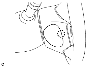
Disengage the claw and remove the lower No. 3 steering wheel cover.
RADIO ANTENNA CORD > REMOVAL |
| 1. PRECAUTION |
| 2. POSITION FRONT WHEELS STRAIGHT AHEAD |
| 3. DISCONNECT CABLE FROM NEGATIVE BATTERY TERMINAL |
| 4. REMOVE LOWER NO. 3 STEERING WHEEL COVER |
|
Disengage the claw and remove the lower No. 3 steering wheel cover.
| 5. REMOVE LOWER NO. 2 STEERING WHEEL COVER |
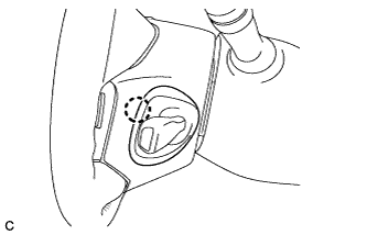 |
Disengage the claw and remove the lower No. 2 steering wheel cover.
| 6. REMOVE STEERING PAD |
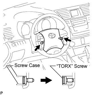 |
Using a "TORX" socket wrench (T30), loosen the 2 "TORX" screws until the groove along the screw circumference catches on the screw case.
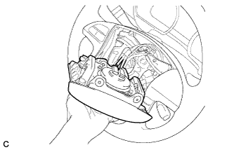 |
Pull out the steering pad from the steering wheel assembly and support the steering pad with one hand as shown in the illustration.
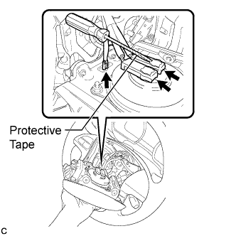 |
Disconnect the horn connector from the steering pad.
Using a screwdriver with the tip wrapped with protective tape, disconnect the 2 airbag connectors and remove the steering pad.
| 7. REMOVE STEERING WHEEL ASSEMBLY |
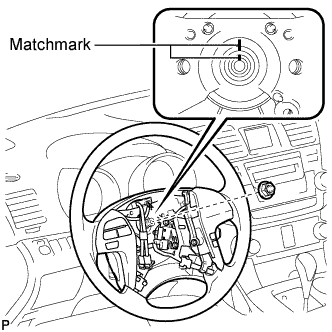 |
Remove the steering wheel assembly set nut.
Put matchmarks on the steering wheel assembly and the steering main shaft.
Disconnect the connectors from the spiral cable.
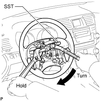 |
Using SST, remove the steering wheel assembly.
| 8. REMOVE STEERING COLUMN COVER |
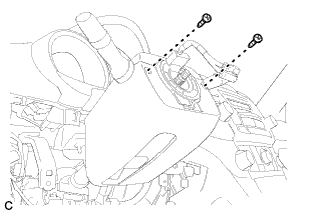 |
Remove the 2 screws.
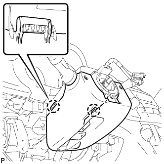 |
Disengage the 2 claws to remove the lower steering column cover.
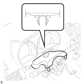 |
Disengage the claw to remove the upper steering column cover.
| 9. REMOVE TURN SIGNAL SWITCH ASSEMBLY WITH SPIRAL CABLE SUB-ASSEMBLY |
Disconnect the connectors from the turn signal switch assembly with spiral cable sub-assembly.
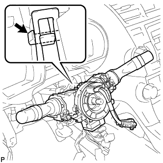 |
Using pliers, grip the claws of the clip and remove the turn signal switch assembly with spiral cable sub-assembly.
| 10. REMOVE INSTRUMENT CLUSTER FINISH PANEL ASSEMBLY |
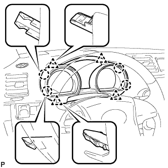 |
Disengage the 4 claws and 4 clips, and remove the instrument cluster finish panel assembly.
| 11. REMOVE COMBINATION METER ASSEMBLY |
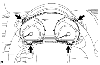 |
Remove the 4 screws.
Disconnect the connector and remove the combination meter assembly.
| 12. REMOVE CENTER INSTRUMENT PANEL REGISTER ASSEMBLY |
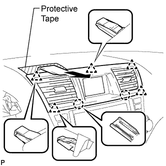 |
Apply protective tape to the areas shown in the illustration.
Using a moulding remover, disengage the 2 claws and 5 clips, and then remove the center instrument panel register assembly as shown in the illustration.
| 13. REMOVE CENTER INSTRUMENT CLUSTER FINISH PANEL ASSEMBLY |
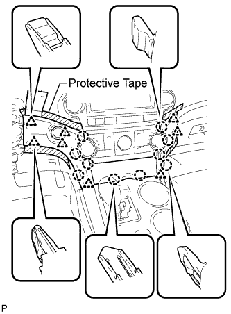 |
Apply protective tape to the areas shown in the illustration.
Using a moulding remover, disengage the 10 claws and 8 clips starting from the upper part of the center instrument cluster finish panel assembly.
Disconnect each connector and remove the center instrument cluster finish panel assembly.
| 14. REMOVE HEATER CONTROL AND ACCESSORY ASSEMBLY (for Manual Air Conditioning System) |
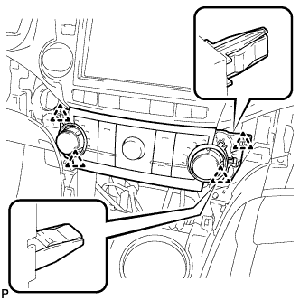 |
Disengage the 4 clips and remove the heater control and accessory assembly.
Disconnect the connector.
| 15. REMOVE AIR CONDITIONING CONTROL ASSEMBLY (for Automatic Air Conditioning System) |
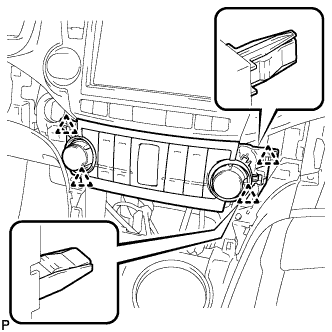 |
Disengage the 4 clips and remove the air conditioning control assembly.
Disconnect the connector.
| 16. REMOVE RADIO RECEIVER ASSEMBLY WITH BRACKET (w/o Navigation System) |
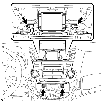 |
Remove the 4 bolts.
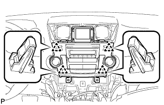 |
Pull the radio receiver assembly with bracket toward the rear of the vehicle and disengage the 4 clips.
Disconnect each connector and remove the radio receiver assembly with bracket.
| 17. REMOVE NAVIGATION RECEIVER ASSEMBLY WITH BRACKET (w/ Navigation System) |
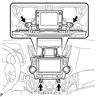 |
Remove the 4 bolts.
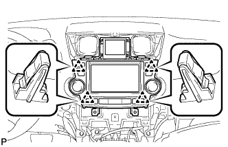 |
Pull the navigation receiver assembly with bracket toward the rear of the vehicle and disengage the 4 clips.
Disconnect each connector and remove the navigation receiver assembly with bracket.
| 18. REMOVE FRONT DOOR SCUFF PLATE LH |
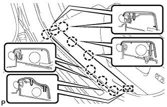 |
Disengage the 8 claws and guide, and remove the front door scuff plate LH.
| 19. REMOVE COWL SIDE TRIM SUB-ASSEMBLY LH |
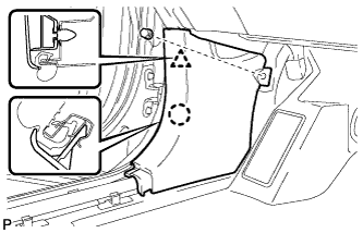 |
Remove the clip.
Disengage the clip and claw, and remove the cowl side trim sub-assembly LH.
| 20. REMOVE LOWER INSTRUMENT PANEL FINISH PANEL SUB-ASSEMBLY |
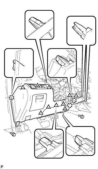 |
Remove the 2 bolts <B>.
Disengage the 3 claws and 10 clips.
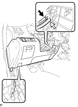 |
Disconnect each connector and the aspirator duct.
Disconnect the hood lock control cable assembly and remove the lower instrument panel finish panel sub-assembly.
| 21. REMOVE FRONT DOOR SCUFF PLATE RH |
| 22. REMOVE COWL SIDE TRIM SUB-ASSEMBLY RH |
| 23. REMOVE NO. 2 INSTRUMENT PANEL UNDER COVER SUB-ASSEMBLY |
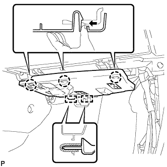 |
Disengage the 3 claws.
Disengage the 2 guides and remove the No. 2 instrument panel under cover sub-assembly.
| 24. REMOVE LOWER INSTRUMENT PANEL SUB-ASSEMBLY |
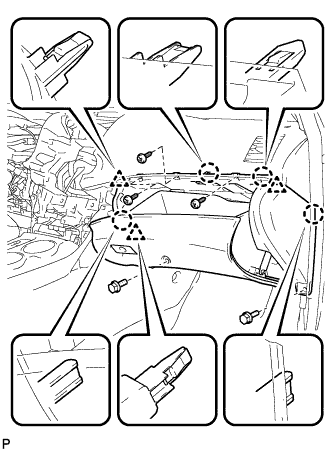 |
Remove the 2 bolts <B> and 3 screws <E>.
Disengage the 4 claws and 3 clips.
Disconnect each connector and clamp, and remove the lower instrument panel sub-assembly.
| 25. REMOVE UPPER CONSOLE PANEL SUB-ASSEMBLY |
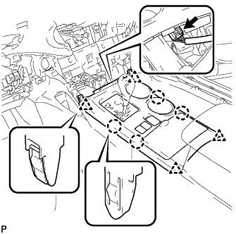 |
Disengage the 4 claws and 4 clips.
Disconnect the connector and remove the upper console panel sub-assembly.
| 26. REMOVE NO. 2 CONSOLE BOX DUCT (w/o Rear Air Conditioning System) |
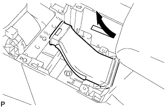 |
Remove the No. 2 console box duct as shown in the illustration.
| 27. REMOVE LOWER REAR CONSOLE BOX |
Remove the lower rear console box.
| 28. REMOVE CONSOLE BOX ASSEMBLY (w/o Rear Air Conditioning System) |
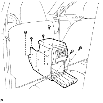 |
Remove the 4 bolts and 2 screws.
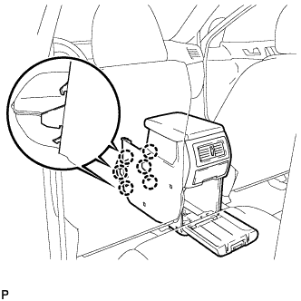 |
Disengage the 6 claws and remove the console box assembly.
| 29. REMOVE CONSOLE BOX ASSEMBLY (w/ Rear Air Conditioning System) |
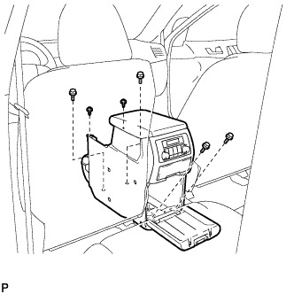 |
Remove the 4 bolts and 2 screws.
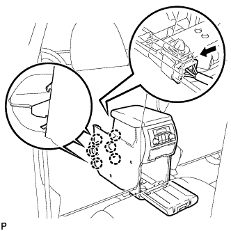 |
Disconnect the connector.
Disengage the 6 claws, and remove the console box assembly.
| 30. REMOVE FRONT NO. 1 CONSOLE BOX INSERT |
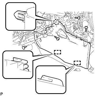 |
Using a clip remover, remove the 2 clips.
Remove the 3 screws <E>.
Disengage the claw and 2 guides, and then remove the front No. 1 console box insert.
| 31. REMOVE FRONT NO. 2 CONSOLE BOX INSERT |
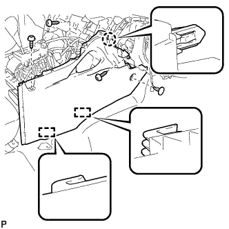 |
Using a clip remover, remove the clip.
Remove the 3 screws <E>.
Disengage the claw and 2 guides, and then remove the front No. 2 console box insert.
| 32. REMOVE POWER SWITCH |
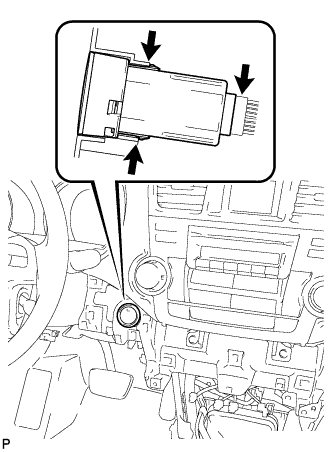 |
Disconnect the switch connector.
Disengage the 2 claws and remove the switch.
| 33. REMOVE FRONT DOOR OPENING TRIM WEATHERSTRIP LH |
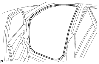 |
Remove the front door opening trim weatherstrip LH.
| 34. REMOVE FRONT PILLAR GARNISH LH |
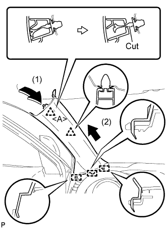 |
Pull the upper part of the garnish toward the inside of the cabin and disengage the 2 clips.
Cut off the clip <A>.
Disengage the 3 guides and remove the front pillar garnish LH.
Remove the clip <A>.
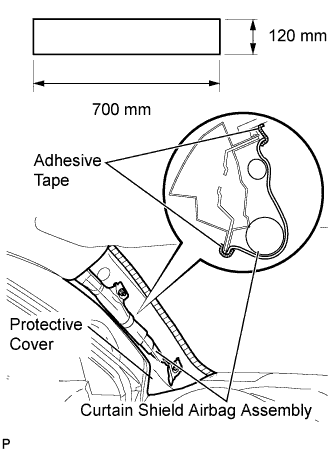 |
Protect the curtain shield airbag assembly.
Cover the airbag with a 700 mm (27.56 in.) x 120 mm (4.72 in.) cloth or piece of nylon and fix the ends of the cover with tape, as shown in the illustration.
| 35. REMOVE FRONT DOOR OPENING TRIM WEATHERSTRIP RH |
| 36. REMOVE FRONT PILLAR GARNISH RH |
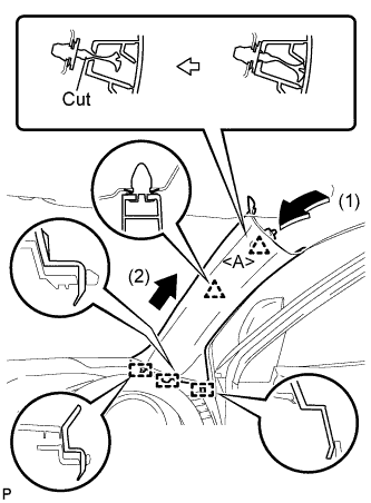 |
Pull the upper part of the garnish toward the inside of the cabin and disengage the 2 clips.
Cut off the clip <A>.
Disengage the 3 guides and remove the front pillar garnish RH.
Remove the clip <A>.
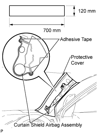 |
Protect the curtain shield airbag assembly.
Cover the airbag with a 700 mm (27.56 in.) x 120 mm (4.72 in.) cloth or piece of nylon and fix the ends of the cover with tape, as shown in the illustration.
| 37. REMOVE NO. 1 INSTRUMENT PANEL SPEAKER PANEL SUB-ASSEMBLY |
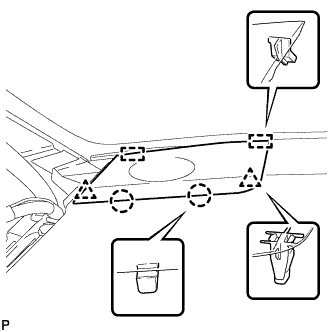 |
Disengage the 2 claws and 2 clips.
Disengage the 2 guides and remove the No. 1 instrument panel speaker panel sub-assembly.
| 38. REMOVE FRONT NO. 2 SPEAKER ASSEMBLY (for LH Side) |
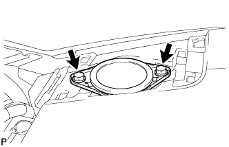 |
Remove the 2 bolts and front No. 2 speaker assembly.
Disconnect the connector.
| 39. REMOVE NO. 2 INSTRUMENT PANEL SPEAKER PANEL SUB-ASSEMBLY |
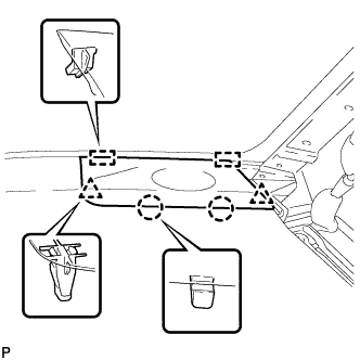 |
Disengage the 2 claws and 2 clips.
Disengage the 2 guides and remove the No. 2 instrument panel speaker panel sub-assembly.
| 40. REMOVE FRONT NO. 2 SPEAKER ASSEMBLY (for RH Side) |
| 41. DISCONNECT INSTRUMENT PANEL WIRE ASSEMBLY |
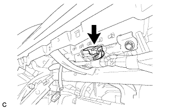 |
Disconnect the connector.
| 42. REMOVE INSTRUMENT PANEL SAFETY PAD ASSEMBLY |
Disconnect each connector.
Remove the 2 passenger airbag bolts <A>.
Disengage each clamp.
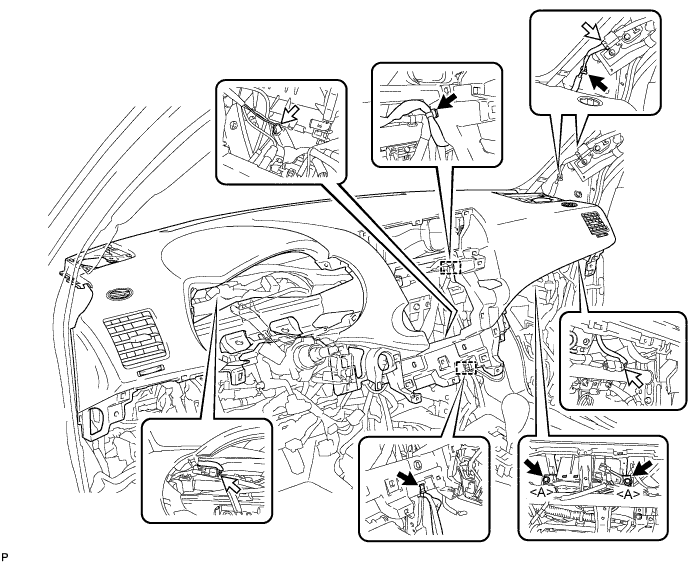
Remove the 2 clips.
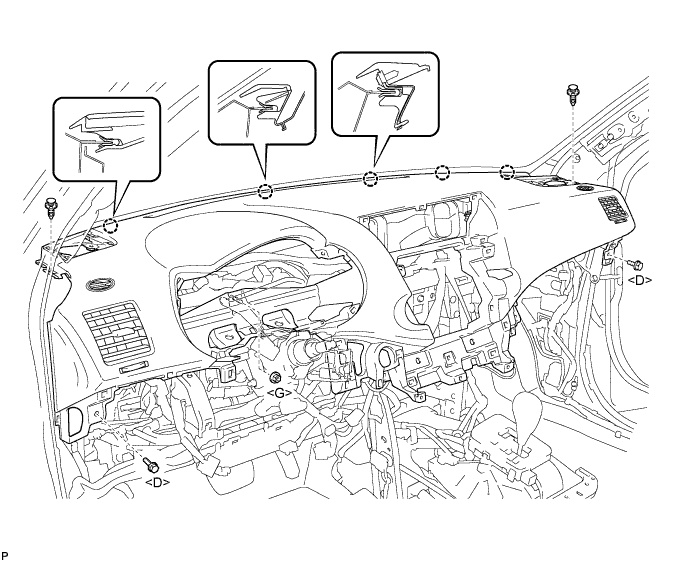
Remove the 2 bolts <D> and nut <G>.
Disengage the 5 claws and remove the instrument panel safety pad assembly.
| 43. REMOVE NO. 1 HEATER TO REGISTER DUCT |
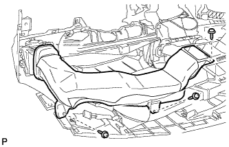 |
Remove the 3 screws <E> and the No. 1 heater to register duct.
| 44. REMOVE NO. 4 HEATER TO REGISTER DUCT |
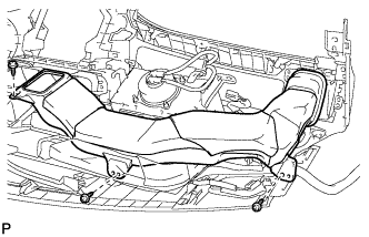 |
Remove the 3 screws <E> and the No. 4 heater to register duct.
| 45. REMOVE SIDE NO. 1 DEFROSTER NOZZLE DUCT |
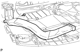 |
Remove the screw <E> and the side No. 1 defroster nozzle duct.
| 46. REMOVE SIDE NO. 2 DEFROSTER NOZZLE DUCT |
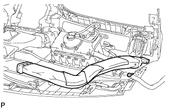 |
Remove the screw <E> and the side No. 2 defroster nozzle duct.
| 47. REMOVE DEFROSTER NOZZLE ASSEMBLY |
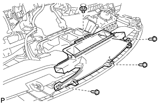 |
Remove the clip.
Remove the 3 screws <E> and the defroster nozzle assembly.
| 48. REMOVE CENTER HEATER TO REGISTER SUB DUCT |
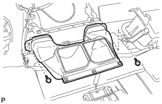 |
Remove the 2 screws <E> and the center heater to register sub duct.
| 49. REMOVE NAVIGATION ANTENNA ASSEMBLY (w/ Navigation System) |
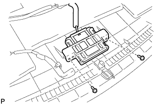 |
Remove the 2 screws and separate the navigation antenna assembly.
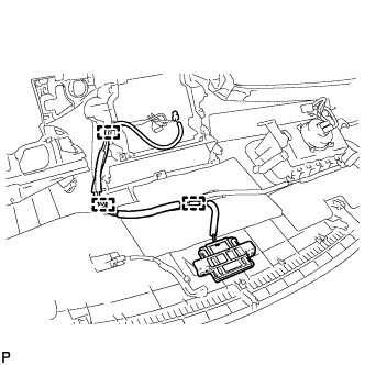 |
Disengage the 3 clamps and remove the navigation antenna assembly.
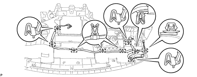
| 50. REMOVE ANTENNA CORD SUB-ASSEMBLY |
Disengage the 9 clamps and remove the antenna cord sub-assembly.
| 51. REMOVE REAR CENTER SEAT ASSEMBLY |
| 52. REMOVE REAR SEAT HEADREST ASSEMBLY (for LH Side) |
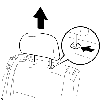 |
Press the headrest support button and pull up the headrest to its highest position as shown in the illustration.
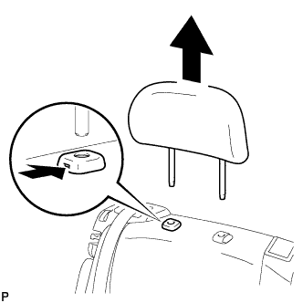 |
Insert a finger or screwdriver into the hole to release the lock. Pull the headrest up as shown in the illustration to remove it.
| 53. REMOVE REAR SEAT TRACK BRACKET COVER LH |
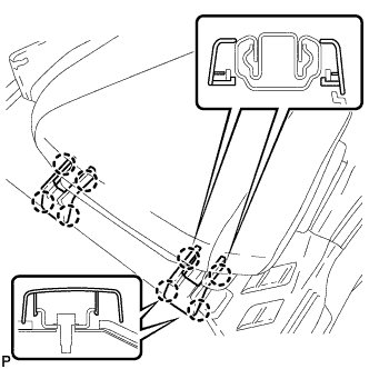 |
Disengage the 8 claws and remove the 2 rear seat track bracket covers.
| 54. REMOVE REAR OUTER TRACK BRACKET COVER LH |
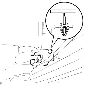 |
Disengage the 4 claws and remove the rear outer track bracket cover.
| 55. REMOVE REAR INNER TRACK BRACKET COVER LH |
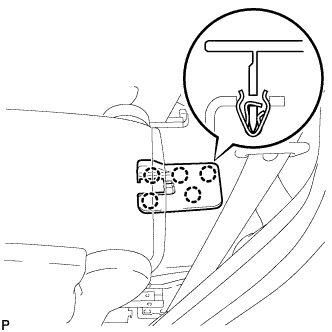 |
Disengage the 5 claws and remove the rear inner track bracket cover.
| 56. REMOVE RECLINING HINGE COVER LH |
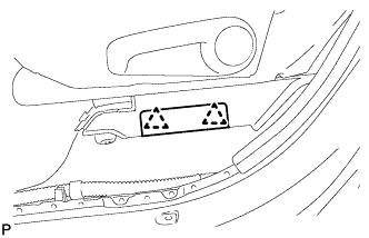 |
Disengage the 2 clips and remove the reclining hinge cover LH.
| 57. REMOVE REAR SEAT LEG SIDE COVER LH |
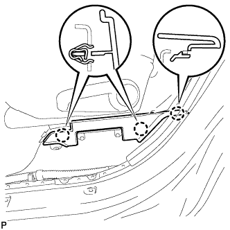 |
Disengage the 3 claws and remove the rear seat leg side cover.
| 58. DISCONNECT REAR NO. 1 SEAT LOCK CABLE ASSEMBLY LH (w/ Remote Folding Function) |
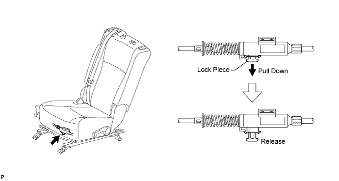
Pull down the adjuster's lock piece to release the lock as shown in the illustration.
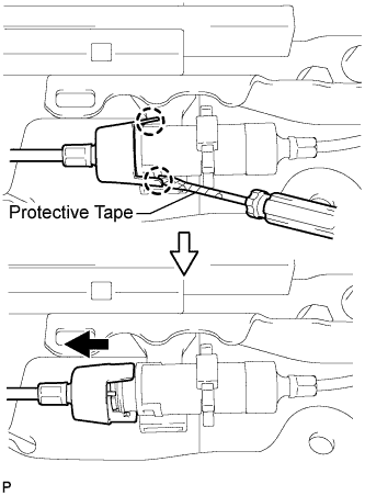 |
Using a screwdriver wrapped with protective tape, disengage the 2 claws as shown in the illustration.
Lift up the seat track adjusting handle to the uppermost position and hold the handle in this position as shown in the illustration.
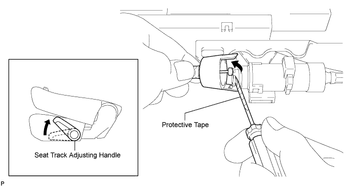
Using a screwdriver wrapped with protective tape, disconnect the rear No. 1 seat lock cable assembly as shown in the illustration.
Using a screwdriver wrapped with protective tape, disconnect the rear seat reclining control cable as shown in the illustration.
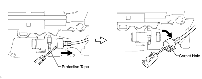
Secure the rear seat reclining control cable with the carpet hole as shown in the illustration.
| 59. REMOVE REAR NO. 1 SEAT ASSEMBLY LH |
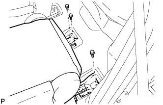 |
Remove the 3 bolts on the rear side of the seat.
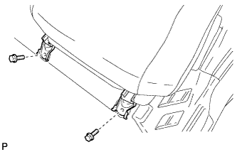 |
Remove the 2 bolts on the front side of the seat and the rear No. 1 seat assembly.
| 60. REMOVE REAR SEAT HEADREST ASSEMBLY (for RH Side) |
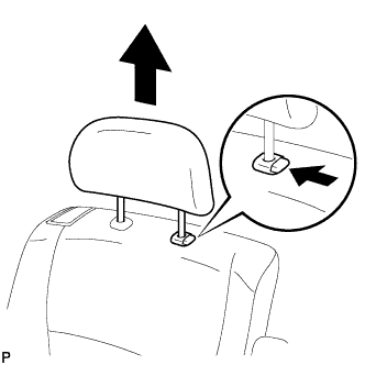 |
Press the headrest support button and pull up the headrest to its highest position as shown in the illustration.
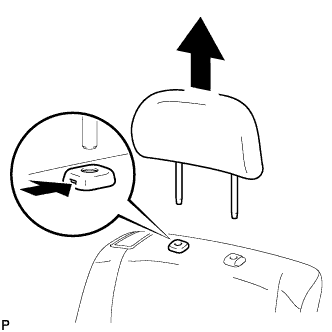 |
Insert a finger or screwdriver into the hole to release the lock. Pull the headrest up as shown in the illustration to remove it.
| 61. REMOVE REAR SEAT TRACK BRACKET COVER RH |
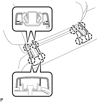 |
Disengage the 8 claws and remove the 2 rear seat track bracket covers.
| 62. REMOVE REAR OUTER TRACK BRACKET COVER RH |
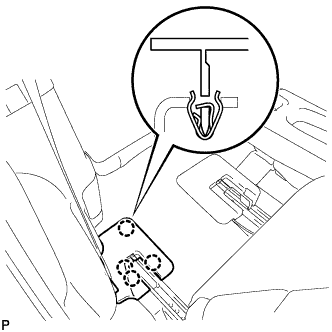 |
Disengage the 4 claws and remove the rear outer track bracket cover.
| 63. REMOVE REAR INNER TRACK BRACKET COVER RH |
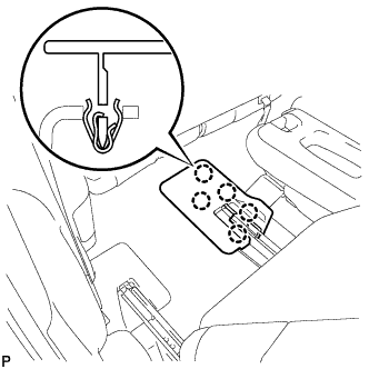 |
Disengage the 5 claws and remove the rear inner track bracket cover.
| 64. REMOVE REAR SEAT LEG SIDE COVER RH |
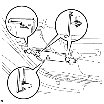 |
Disengage the 3 claws.
Disengage the clip and remove the rear seat leg side cover.
| 65. DISCONNECT REAR NO. 1 SEAT LOCK CABLE ASSEMBLY RH (w/ Remote Folding Function) |
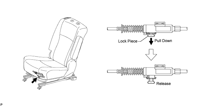
Pull down the adjuster's lock piece to release the lock as shown in the illustration.
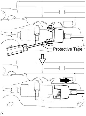 |
Using a screwdriver wrapped with protective tape, disengage the 2 claws as shown in the illustration.
Lift up the seat track adjusting handle to the uppermost position and hold the handle in this position as shown in the illustration.
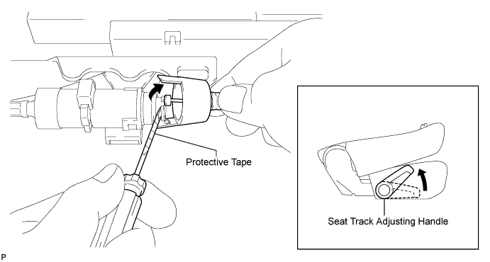
Using a screwdriver wrapped with protective tape, disconnect the rear No. 1 seat lock cable assembly as shown in the illustration.
Using a screwdriver wrapped with protective tape, disconnect the rear seat reclining control cable as shown in the illustration.
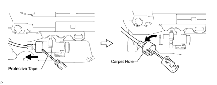
Secure the rear seat reclining control cable with the carpet hole as shown in the illustration.
| 66. REMOVE REAR NO. 1 SEAT ASSEMBLY RH |
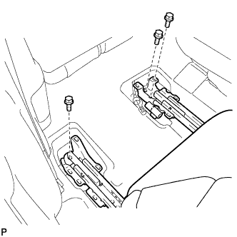 |
Remove the 3 bolts on the rear side of the seat.
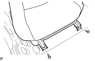 |
Remove the 2 bolts on the front side of the seat and the rear No. 1 seat assembly.
| 67. REMOVE REAR DOOR SCUFF PLATE LH |
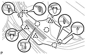 |
Disengage the 5 claws, 3 clips and guide, and remove the rear door scuff plate LH.
| 68. REMOVE REAR DOOR OPENING TRIM WEATHERSTRIP LH |
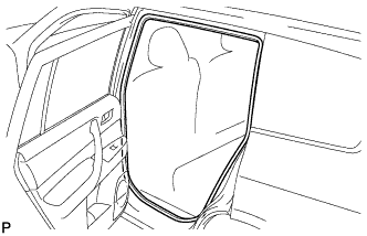 |
Remove the rear door opening trim weatherstrip LH.
| 69. REMOVE LOWER CENTER PILLAR GARNISH LH |
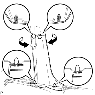 |
Disengage the 2 claws and 2 clips, and remove the lower center pillar garnish LH.
| 70. DISCONNECT FRONT SEAT OUTER BELT ASSEMBLY LH |
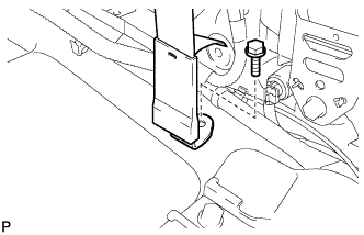 |
Remove the bolt and disconnect the floor end of the front seat outer belt assembly.
| 71. REMOVE CENTER PILLAR GARNISH LH |
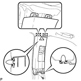 |
Remove the screw and clip.
Disengage the 2 guides and clip, and remove the center pillar garnish LH.
| 72. REMOVE REAR DOOR SCUFF PLATE RH |
| 73. REMOVE REAR DOOR OPENING TRIM WEATHERSTRIP RH |
| 74. REMOVE LOWER CENTER PILLAR GARNISH RH |
| 75. DISCONNECT FRONT SEAT OUTER BELT ASSEMBLY RH |
| 76. REMOVE CENTER PILLAR GARNISH RH |
| 77. REMOVE DECK BOARD ASSEMBLY |
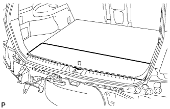 |
Remove the deck board assembly.
| 78. REMOVE NO. 3 DECK BOARD SUB-ASSEMBLY |
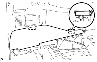 |
Disengage the 2 guides and remove the No. 3 deck board sub-assembly.
| 79. REMOVE NO. 2 DECK BOARD SUB-ASSEMBLY |
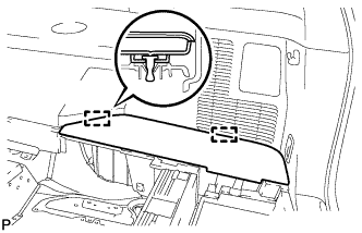 |
Disengage the 2 guides and remove the No. 2 deck board sub-assembly.
| 80. REMOVE TONNEAU COVER ASSEMBLY (w/ Tonneau Cover) |
Remove the tonneau cover assembly.
| 81. REMOVE REAR NO. 1 FLOOR BOARD (w/o Rear No. 2 Seat) |
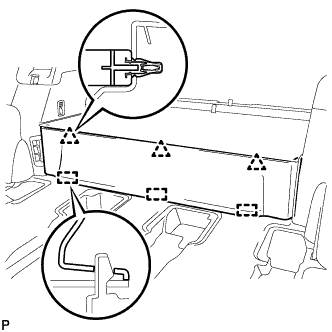 |
Disengage the 3 clips and the 3 guides, and remove the rear No. 1 floor board.
| 82. REMOVE REAR SEAT SIDE COVER LH (w/ Rear No. 2 Seat) |
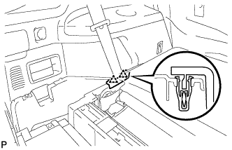 |
Disengage the 2 clips and remove the rear seat side cover LH.
| 83. REMOVE DECK SIDE TRIM BOX LH |
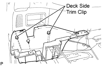 |
Remove the 2 deck side trim clips and clip.
Remove the deck side trim box LH as shown in the illustration.
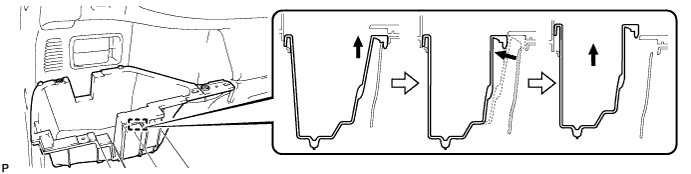
| 84. REMOVE REAR SEAT SIDE COVER RH (w/ Rear No. 2 Seat) |
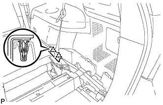 |
Disengage the 2 clips and remove the rear seat side cover RH.
| 85. REMOVE JACK CARRIER SUPPORT |
| 86. REMOVE JACK CARRIER CUSHION |
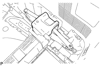 |
Remove the jack carrier cushion.
| 87. REMOVE JACK ASSEMBLY |
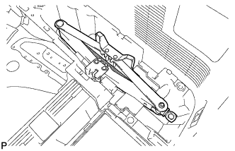 |
Remove the jack assembly.
| 88. REMOVE JACK CARRIER ASSEMBLY |
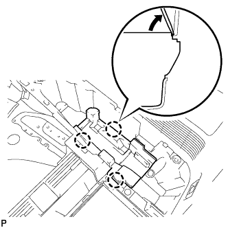 |
Using a screwdriver, disengage the 3 claws and remove the jack carrier assembly.
| 89. REMOVE DECK SIDE TRIM BOX RH |
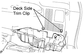 |
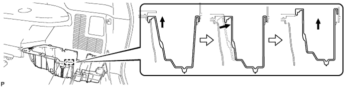
Remove the 2 deck side trim clips and clip.
Remove the deck side trim box RH as shown in the illustration.
| 90. REMOVE DECK FLOOR BOARD ASSEMBLY (w/o Rear No. 2 Seat) |
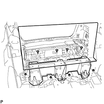 |
Remove the 4 bolts and 4 nuts.
Remove the deck floor board assembly.
| 91. REMOVE REAR MAT |
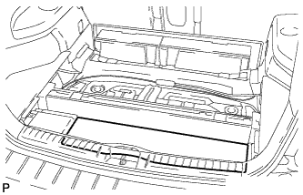 |
Remove the rear mat.
| 92. REMOVE DECK FLOOR BOARD ASSEMBLY (w/ Rear No. 2 Seat) |
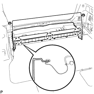 |
Disengage the 3 claws.
Remove the 2 nuts and the deck floor board assembly.
| 93. REMOVE REAR DECK FLOOR BOX (w/o Rear No. 2 Seat) |
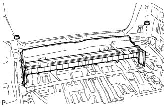 |
Remove the 2 nuts and the deck floor box.
| 94. REMOVE REAR NO. 2 SEAT INNER BELT ASSEMBLY (w/ Rear No. 2 Seat) |
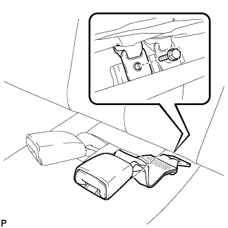 |
Remove the bolt and rear No. 2 seat inner belt assembly.
| 95. DISCONNECT REAR SEAT LAP TYPE BELT ASSEMBLY LH (w/ Rear No. 2 Seat) |
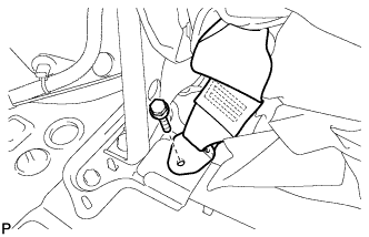 |
Remove the bolt and disconnect the rear seat lap type belt assembly LH.
| 96. DISCONNECT REAR SEAT LAP TYPE BELT ASSEMBLY RH (w/ Rear No. 2 Seat) |
| 97. REMOVE REAR NO. 2 SEAT ASSEMBLY (w/ Rear No. 2 Seat) |
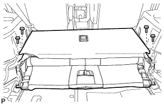 |
Remove the 4 bolts and the rear No. 2 seat assembly.
| 98. REMOVE REAR FLOOR FINISH PLATE |
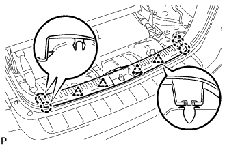 |
Disengage the 4 clips and the 4 claws, and remove the rear floor finish plate.
| 99. REMOVE DECK SIDE TRIM COVER LH |
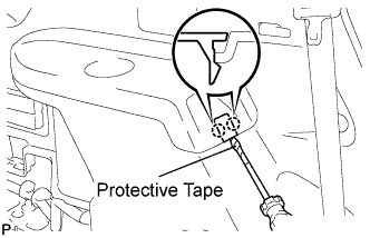 |
Using a screwdriver, disengage the 2 claws and remove the deck side trim cover LH.
| 100. REMOVE DECK SIDE TRIM LH |
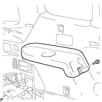 |
Remove the bolt.
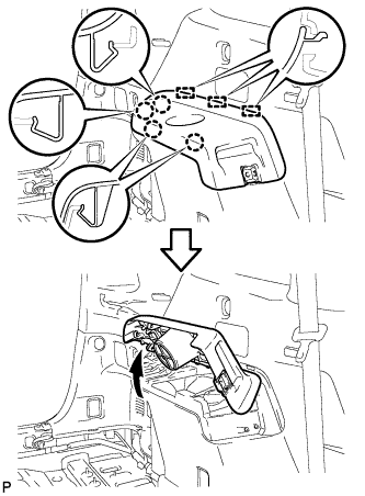 |
Disengage the 4 claws and the 3 guides, and remove the deck side trim LH as shown in the illustration.
| 101. REMOVE SIDE TRIM COVER LH (w/o Rear Seat Entertainment System) |
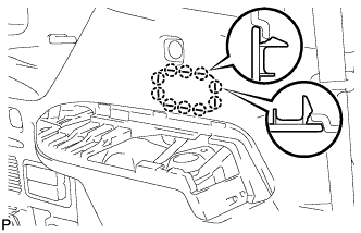 |
Disengage the 10 claws and remove the side trim cover LH.
| 102. REMOVE POWER OUTLET SOCKET BEZEL (w/ Rear Seat Entertainment System) |
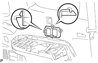 |
Disengage the 4 claws.
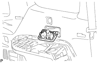 |
Disconnect each connector and remove the power outlet socket bezel.
| 103. REMOVE REAR COMBINATION LIGHT SERVICE COVER LH |
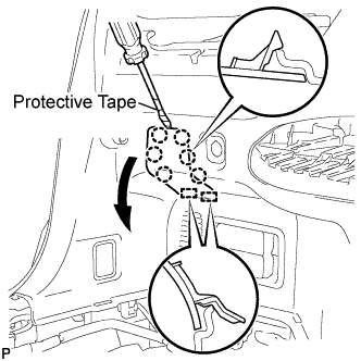 |
Using a screwdriver, disengage the 6 claws and 2 guides, and remove the rear combination light service cover LH.
| 104. REMOVE REAR POWER POINT SOCKET ASSEMBLY |
Disconnect the connector.
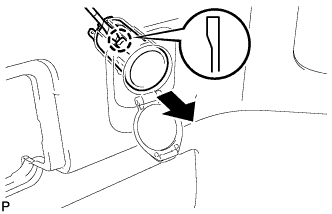 |
Disengage the claw and remove the rear power point socket assembly.
| 105. REMOVE REAR POWER OUTLET SOCKET COVER |
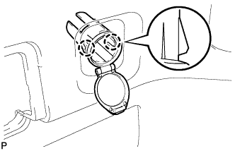 |
Disengage the 2 claws and remove the rear power outlet socket cover.
| 106. REMOVE REAR DECK TRIM COVER (w/o Remote Folding Function) |
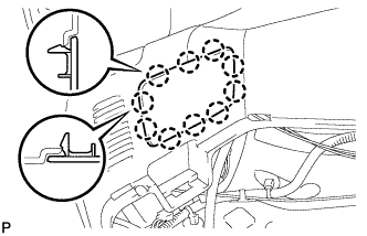 |
Disengage the 10 claws and remove the rear deck trim cover.
| 107. REMOVE RECLINING REMOTE CONTROL LEVER BEZEL LH (w/ Remote Folding Function) |
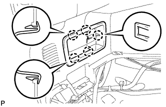 |
Disengage the 5 claws and remove the reclining remote control lever bezel LH.
| 108. REMOVE ROPE HOOK ASSEMBLY (for LH Side) |
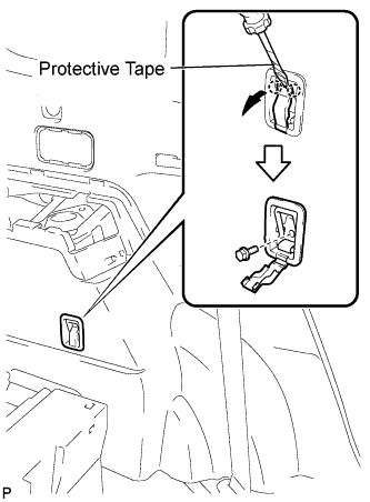 |
for Front Side:
Using a screwdriver, disengage the 2 claws.
Remove the bolt and the rope hook assembly.
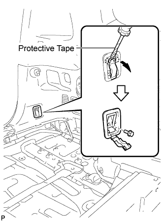 |
for Rear Side:
Using a screwdriver, disengage the 2 claws.
Remove the bolt and rope hook assembly.
| 109. REMOVE NO. 2 DECK SIDE TRIM HOOK |
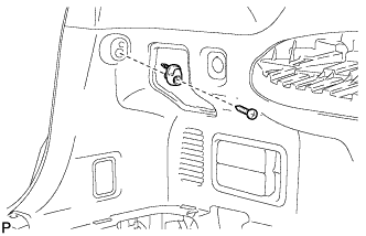 |
Remove the screw and the No. 2 deck side trim hook.
| 110. REMOVE FRONT DECK SIDE TRIM COVER LH |
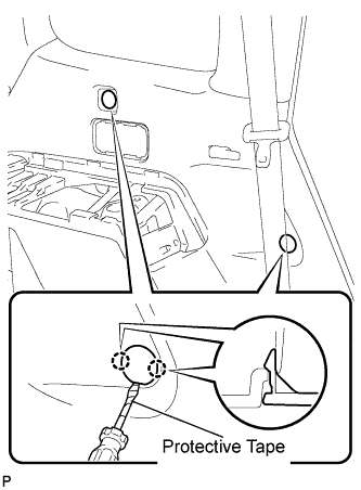 |
Using a screwdriver, disengage the 4 claws and remove the 2 front deck side trim covers LH.
| 111. DISCONNECT REAR NO. 1 SEAT OUTER BELT ASSEMBLY LH |
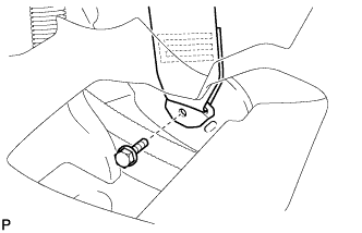 |
Remove the bolt and disconnect the floor end of the rear No. 1 seat outer belt assembly.
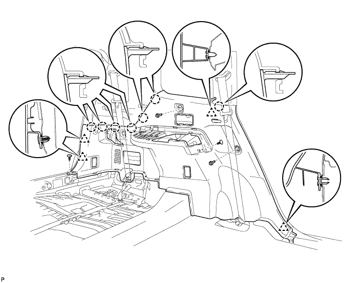
| 112. REMOVE DECK TRIM SIDE PANEL ASSEMBLY LH |
Remove the 2 bolts.
Remove the 2 clips.
Disengage the 7 claws and 4 clips, and remove the deck trim side panel assembly LH.
| 113. REMOVE QUARTER PILLAR GARNISH LH |
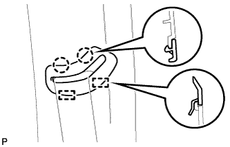 |
Disengage the 2 claws and 2 guides, and remove the No. 1 seat outer belt guide.
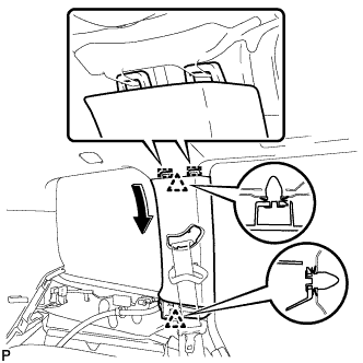 |
Disengage the 2 clips and the 2 guides, and remove the quarter pillar garnish LH.
| 114. REMOVE ROOF SIDE INNER GARNISH ASSEMBLY LH (w/o Power Back Door) |
w/o Rear No. 2 Seat:
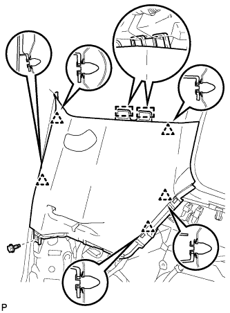 |
Remove the bolt.
Disengage the 5 clips and 2 guides, and remove the roof side inner garnish assembly LH.
w/ Rear No. 2 Seat:
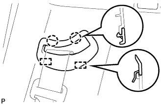 |
Disengage the 2 claws and 2 guides, and remove the rear No. 2 seat outer belt guide.
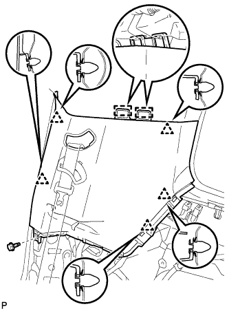 |
Remove the bolt.
Disengage the 5 clips and 2 guides, and remove the roof side inner garnish assembly LH.
| 115. REMOVE ROOF SIDE INNER GARNISH ASSEMBLY LH (w/ Power Back Door) |
w/o Rear No. 2 Seat:
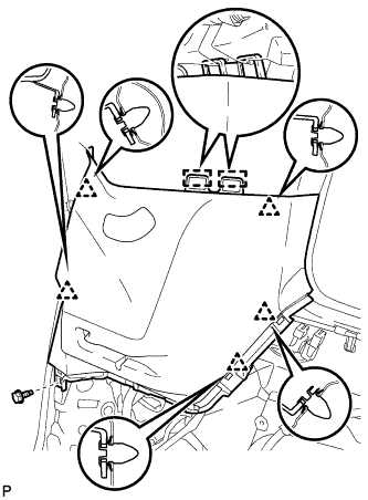 |
Remove the bolt.
Disengage the 5 clips and 2 guides, and remove the roof side inner garnish assembly LH.
w/ Rear No. 2 Seat:
|
Disengage the 2 claws and 2 guides, and remove the rear No. 2 seat outer belt guide.
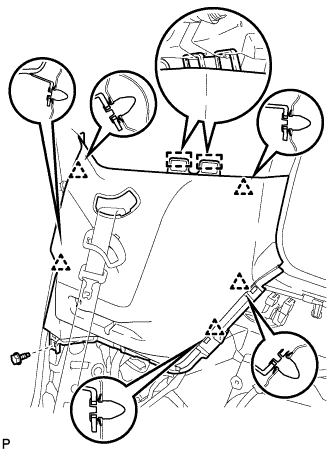 |
Remove the bolt.
Disengage the 5 clips and 2 guides, and remove the roof side inner garnish assembly LH.
| 116. REMOVE REAR SEAT SIDE GARNISH CAP (w/o Rear Air Conditioning System) |
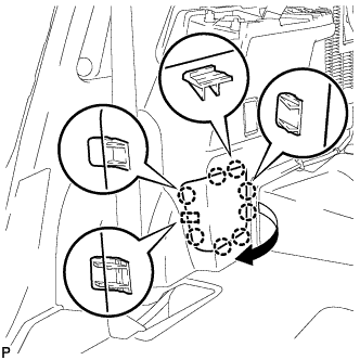 |
Disengage the 8 claws and guide, and remove the rear seat side garnish cap.
| 117. REMOVE REAR SEAT SIDE GARNISH CAP (w/ Rear Air Conditioning System) |
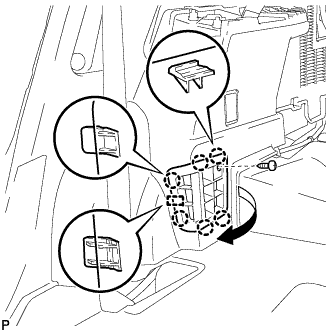 |
Remove the screw.
Disengage the 6 claws and the guide, and remove the rear seat side garnish cap.
| 118. REMOVE DECK SIDE TRIM COVER RH |
| 119. REMOVE DECK SIDE TRIM RH |
| 120. REMOVE SIDE TRIM COVER RH (w/o Rear Automatic Air Conditioning System) |
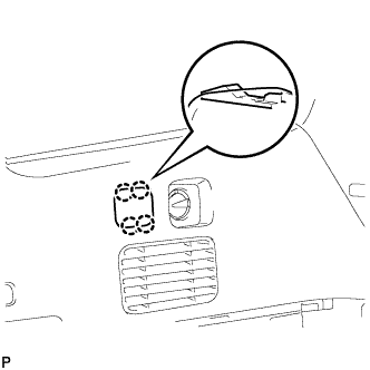 |
Disengage the 4 claws and remove the side trim cover RH.
| 121. REMOVE REAR ROOM TEMPERATURE SENSOR (w/ Rear Automatic Air Conditioning System) |
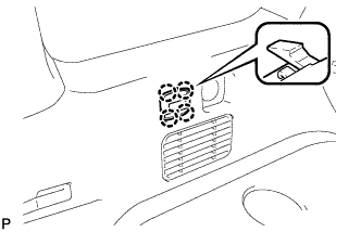 |
Disengage the 4 claws and remove the rear room temperature sensor.
Disconnect the connector.
| 122. REMOVE REAR COMBINATION LIGHT SERVICE COVER RH |
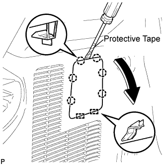 |
Using a screwdriver, disengage the 6 claws and the 2 guides, and remove the rear combination light service cover RH.
| 123. REMOVE ROPE HOOK ASSEMBLY (for RH Side) |
| 124. REMOVE NO. 1 LUGGAGE COMPARTMENT TRIM HOOK |
| 125. REMOVE FRONT DECK SIDE TRIM COVER RH |
| 126. DISCONNECT REAR NO. 1 SEAT OUTER BELT ASSEMBLY RH |
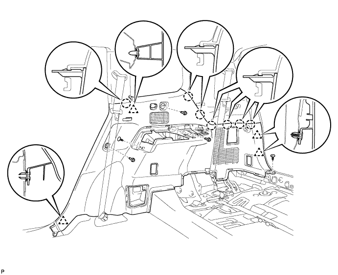
| 127. REMOVE DECK TRIM SIDE PANEL ASSEMBLY RH |
Remove the 3 bolts.
Remove the 2 clips.
Disengage the 7 claws and 4 clips, and remove the deck trim side panel assembly RH.
| 128. REMOVE QUARTER PILLAR GARNISH RH |
| 129. REMOVE ROOF SIDE INNER GARNISH ASSEMBLY RH (w/o Rear No. 2 Seat) |
| 130. REMOVE ROOF SIDE INNER GARNISH ASSEMBLY RH (w/ Rear No. 2 Seat) |
| 131. REMOVE ROOF CONSOLE BOX ASSEMBLY |
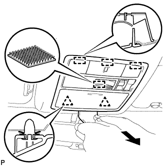 |
Using a moulding remover, disengage the 2 clips, 3 guides and fastener.
Disconnect the connector and remove the roof console box assembly.
| 132. REMOVE VISOR BRACKET COVER (for LH Side) |
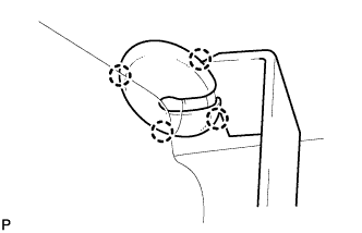 |
Using a moulding remover, disengage the 4 claws and remove the visor bracket cover.
| 133. REMOVE VISOR ASSEMBLY LH |
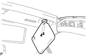 |
Remove the 2 screws and remove the visor assembly LH.
| 134. REMOVE VISOR BRACKET COVER (for RH Side) |
| 135. REMOVE VISOR ASSEMBLY RH |
| 136. REMOVE INNER REAR VIEW MIRROR STAY HOLDER COVER (w/ EC Mirror) |
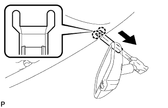 |
Disengage the 2 claws and slide the inner rear view mirror stay holder cover as shown in the illustration.
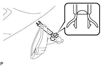 |
Disengage the 2 claws and remove the inner rear view mirror stay holder cover.
| 137. REMOVE NO. 1 ROOM LIGHT ASSEMBLY (for Standard) |
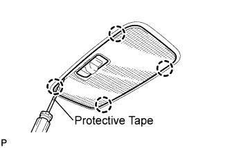 |
Using a screwdriver, disengage the 4 claws and remove the lens cover.
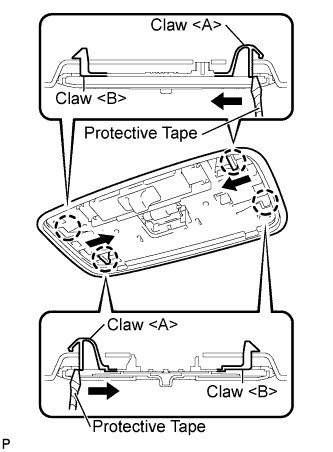 |
Using a screwdriver, disengage the 2 claws <A> as shown in the illustration.
Disengage the 2 claws <B>.
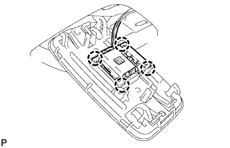 |
Using a screwdriver, disengage the 4 claws and remove the No. 1 room light assembly.
| 138. REMOVE NO. 1 ROOM LIGHT ASSEMBLY (for Independent Type) |
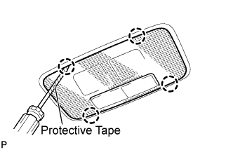 |
Using a screwdriver, disengage the 4 claws and remove the lens cover.
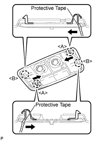 |
Using a screwdriver, disengage the 2 claws <A> as shown in the illustration.
Disengage the 2 claws <B>.
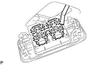 |
Using a screwdriver, disengage the 8 claws and remove the No. 1 room light assembly.
| 139. REMOVE NO. 2 ROOM LIGHT ASSEMBLY |
|
Using a screwdriver, disengage the 4 claws and remove the lens cover.
|
Using a screwdriver, disengage the 2 claws <A> as shown in the illustration.
Disengage the 2 claws <B>.
|
Using a screwdriver, disengage the 4 claws and remove the No. 2 room light assembly.
| 140. REMOVE TELEVISION BASE (w/ Rear Seat Entertainment System) |
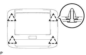 |
Disengage the 4 clips and remove the television base.
| 141. REMOVE TELEVISION DISPLAY ASSEMBLY (w/ Rear Seat Entertainment System) |
Disconnect the connector.
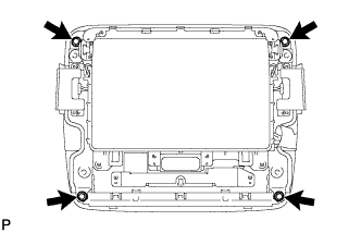 |
Remove the 4 bolts.
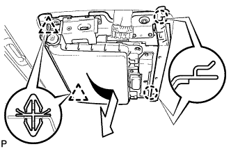 |
Disengage the 2 clips and 2 claws, and then remove the television display.
| 142. REMOVE FRONT ASSIST GRIP SUB-ASSEMBLY (w/o Sliding Roof) |
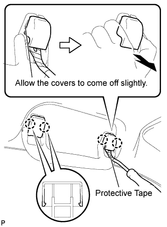 |
Using a clip remover, disengage the 4 claws.
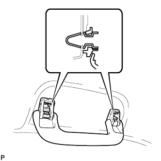 |
Pull off the 2 assist grip covers by hand.
Disengage the 2 clips and remove the front assist grip sub-assembly.
Remove the 2 clips from the vehicle body.
| 143. REMOVE REAR ASSIST GRIP SUB-ASSEMBLY (w/o Sliding Roof) |
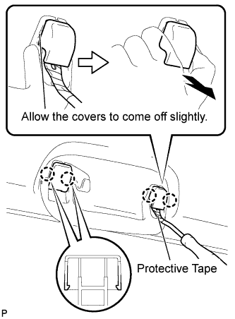 |
Using a clip remover, disengage the 4 claws.
Pull off the 2 assist grip covers by hand.
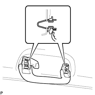 |
Disengage the 2 clips and remove the rear assist grip sub-assembly.
Remove the 2 clips from the vehicle body.
| 144. REMOVE ASSIST GRIP ASSEMBLY (w/ Sliding Roof) |
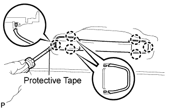 |
Using a screwdriver, disengage the 6 claws and remove the 2 assist grip covers.
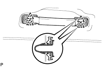 |
Disengage the 4 clips and remove the assist grip assembly.
Remove the 4 clips from the vehicle body.
| 145. REMOVE ROOF HEADLINING TRIM CLIP STOPPER |
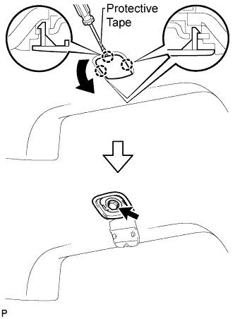 |
Using a screwdriver, disengage the 3 claws.
Remove the bolt and the roof headlining trim clip stopper.
| 146. REMOVE SUN ROOF OPENING TRIM MOULDING (w/ Sliding Roof) |
| 147. REMOVE VISOR HOLDER |
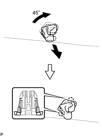 |
Turn the visor holder approximately 45° and pull it out as shown in the illustration.
Disengage the 2 claws and remove the visor holder.
| 148. REMOVE ROOF HEADLINING ASSEMBLY (w/o Sliding Roof) |
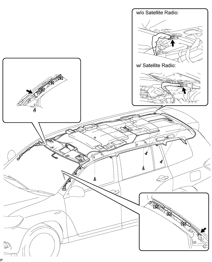
Disconnect the No. 1 roof wire connector and disengage the 3 clamps from the front pillar LH.
Disconnect the No. 2 antenna cord sub-assembly connector, disengage the 3 clamps and remove the bolt from the front pillar RH.
Disconnect the No. 2 antenna cord sub-assembly connector from the rear pillar RH.
Remove the 4 clips.
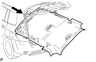 |
Remove the roof headlining assembly from the vehicle through the back door.
| 149. REMOVE ROOF HEADLINING ASSEMBLY (w/ Sliding Roof) |
Disconnect the No. 1 roof wire connectors and disengage the 3 clamps from the front pillar LH.
w/ Rear Seat Entertainment System:
Disconnect the No. 1 roof wire connector from the rear pillar LH.
Disconnect the No. 2 antenna cord sub-assembly connector, disengage the 3 clamps and remove the bolt from the front pillar RH.
Disconnect the No. 2 antenna cord sub-assembly connector from the rear pillar RH.
Disconnect the sliding roof drive gear connector.
Remove the 3 clips.
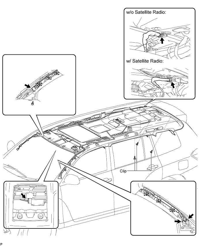
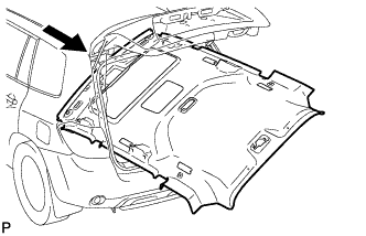 |
Remove the roof headlining assembly from the vehicle through the back door.
| 150. REMOVE NO. 2 ANTENNA CORD SUB-ASSEMBLY |
Peel off the pieces of tape used to secure the antenna cord only enough to allow removal of the antenna cord.
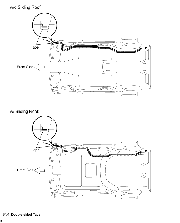
Remove the No. 2 antenna cord sub-assembly from the roof headlining.
| 151. REMOVE SATELLITE RADIO ANTENNA ASSEMBLY (w/ Satellite Radio) |
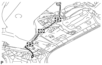 |
Remove the antenna wire from the 3 clamps.
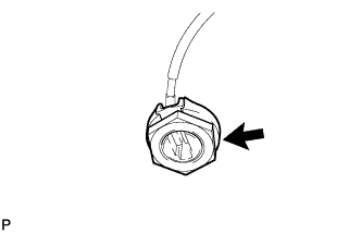 |
Remove the antenna nut.
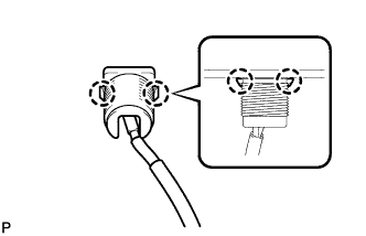 |
Disengage the 2 claws and remove the satellite radio antenna assembly.