DOOR / HATCH POWER BACK DOOR SYSTEM B222B PBD Touch Sensor RH Circuit
DESCRIPTION
This DTC is stored when the multiplex network door ECU detects a malfunction of the power back door sensor assembly RH touch sensor.
| DTC No. | Detection Item | DTC Detection Condition | Trouble Area |
|---|---|---|---|
| B222B | PBD Touch Sensor RH Circuit | The multiplex network door ECU detects a malfunction of the power back door sensor assembly RH touch sensor. | ·
Multiplex network door ECU ·
Power back door sensor assembly RH ·
Wire harness or connector |
WIRING DIAGRAM
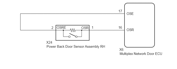
PROCEDURE
Clear the DTCs.
Click hereVehicle Exterior>DOOR / HATCH>POWER BACK DOOR SYSTEM>DTC CHECK / CLEAR
- Body Electrical > Back Door > Clear DTCs
- 50002 159
Check for DTCs.
Click hereVehicle Exterior>DOOR / HATCH>POWER BACK DOOR SYSTEM>DTC CHECK / CLEAR
- Body Electrical > Back Door > Trouble Codes
- 50001 159
- Result:
Result Proceed to DTC B222B is not output A DTC B222B is output B
A
Click hereGeneral>INTRODUCTION>HOW TO TROUBLESHOOT ECU CONTROLLED SYSTEMS>HOW TO PROCEED WITH TROUBLESHOOTING
B
Connect the GTS to the DLC3.
Turn the engine switch on (IG).
Turn the GTS on.
Enter the following menus: Body Electrical / Back Door / Data List.
Read the Data List according to the display on the GTS.
- Body Electrical > Back Door > Data List
-
Tester Display Measurement Item Range Normal Condition Diagnostic Note PBD Touch Sensor (Right) Power back door sensor assembly RH signal ON, OFF or Open ON: Power back door sensor assembly RH pressed
OFF: Power back door sensor assembly RH not pressed
Open: Power back door sensor assembly RH circuit open-
- Body Electrical > Back Door > Data List
-
Tester Display PBD Touch Sensor (Right) - 50003 159 5
- Result:
Result Proceed to On the GTS screen, ON or OFF is displayed accordingly A On the GTS screen, ON or OFF is not displayed accordingly, or Open is displayed for power back door sensor assembly RH B
A
B
Remove the power back door sensor assembly RH.
Click hereVehicle Exterior>DOOR / HATCH>POWER BACK DOOR TOUCH SENSOR>REMOVAL
Inspect the power back door sensor assembly RH.
Click hereVehicle Exterior>DOOR / HATCH>POWER BACK DOOR TOUCH SENSOR>INSPECTION
- Result:
Proceed to OK NG
OK
NG
Disconnect the X6 multiplex network door ECU connector.
Disconnect the X24 power back door sensor assembly RH connector.
Measure the resistance according to the value(s) in the table below.
- Standard Resistance:
Tester Connection Condition Specified Condition X6-16 (OSR) - X24-1 (OSR) Always Below 1 Ω X6-17 (OSE) - X24-2 (OSRE) Always Below 1 Ω X6-16 (OSR) or X24-1 (OSR) - Body ground Always 10 kΩ or higher X6-17 (OSE) or X24-2 (OSRE) - Body ground Always 10 kΩ or higher
- Result:
Proceed to OK NG
OK
NG