RM3160E
_56
Audio / Visual / Telematics
_019700
AUDIO / VIDEO
_0096790
AUDIO AND VISUAL SYSTEM
J
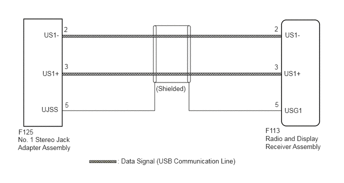
AUDIO / VIDEO AUDIO AND VISUAL SYSTEM Data Signal Circuit between Radio Receiver and Stereo Jack Adapter
DESCRIPTION
The No. 1 stereo jack adapter assembly sends the sound data signal or image data signal from a USB device to the radio and display receiver assembly via this circuit.
WIRING DIAGRAM
0.917,0.646 1.5,0.938
0.583,0.292
10
false
US1-
0.865,2.198 1.448,2.49
0.583,0.292
10
false
UJSS
0.385,2.667 0.969,2.958
0.583,0.292
10
false
F125
0.375,2.823 1.563,3.281
1.188,0.458
10
false
No. 1 Stereo Jack Adapter Assembly
2.448,3.271 5.115,3.625
2.667,0.354
10
false
: Data Signal (USB Communication Line)
5.531,2.635 6.115,2.927
0.583,0.292
10
false
F113
5.531,2.802 6.76,3.24
1.229,0.438
10
false
Radio and Display Receiver Assembly
5.927,2.219 6.51,2.51
0.583,0.292
10
false
USG1
3.25,1.76 4.01,2.094
0.76,0.333
10
false
(Shielded)
1.333,0.531 1.917,0.823
0.583,0.292
10
false
2
1.344,1.302 1.927,1.594
0.583,0.292
10
false
3
1.354,2.104 1.938,2.396
0.583,0.292
10
false
5
0.885,1.448 1.469,1.74
0.583,0.292
10
false
US1+
5.938,0.646 6.521,0.938
0.583,0.292
10
false
US1-
5.917,1.448 6.5,1.74
0.583,0.292
10
false
US1+
5.719,0.521 6.302,0.813
0.583,0.292
10
false
2
5.719,1.313 6.302,1.604
0.583,0.292
10
false
3
5.729,2.094 6.313,2.385
0.583,0.292
10
false
5
PROCEDURE
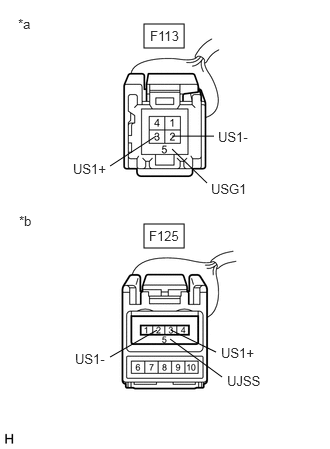
1.CHECK HARNESS AND CONNECTOR (RADIO AND DISPLAY RECEIVER ASSEMBLY - NO. 1 STEREO JACK ADAPTER ASSEMBLY)
a.
Disconnect the F113 radio and display receiver assembly connector.
b.
Disconnect the F125 No. 1 stereo jack adapter assembly connector.
c.
1.5,0.25 1.917,0.5
0.417,0.25
1.5,2.333 1.917,2.583
0.417,0.25
1.792,1.417 2.229,1.417
false
1.146,1.729 1.625,1.417
false
1.146,3.719 1.635,3.438
false
1.781,3.438 2.25,3.667
false
1.771,3.531 2.313,3.927
false
1.792,1.552 2.156,1.906
false
0.188,0.167 0.5,0.323
0.313,0.156
10
false
*a
0.198,2.219 0.51,2.438
0.313,0.219
10
false
*b
1.563,0.292 1.917,0.49
0.354,0.198
10
false
F113
0.76,1.677 1.177,1.927
0.417,0.25
10
false
US1+
2.271,1.344 2.688,1.594
0.417,0.25
10
false
US1-
2.198,1.885 2.615,2.135
0.417,0.25
10
false
USG1
2.302,3.594 2.719,3.844
0.417,0.25
10
false
US1+
2.365,3.885 2.781,4.135
0.417,0.25
10
false
UJSS
0.781,3.656 1.198,3.906
0.417,0.25
10
false
US1-
1.552,2.375 1.906,2.573
0.354,0.198
10
false
F125
| *a | Front view of wire harness connector
(to Radio and Display Receiver Assembly) |
| *b | Front view of wire harness connector
(to No. 1 Stereo Jack Adapter Assembly) |
Measure the resistance according to the value(s) in the table below.
- Standard Resistance:
Tester Connection Condition Specified Condition F113-2 (US1-) - F125-2 (US1-) Always Below 1 Ω F113-3 (US1+) - F125-3 (US1+) Always Below 1 Ω F113-5 (USG1) - F125-5 (UJSS) Always Below 1 Ω F113-2 (US1-) or F125-2 (US1-) - Body ground Always 10 kΩ or higher F113-3 (US1+) or F125-3 (US1+) - Body ground Always 10 kΩ or higher F113-5 (USG1) or F125-5 (UJSS) - Body ground Always 10 kΩ or higher
- Result:
Proceed to OK NG
OK
PROCEED TO NEXT SUSPECTED AREA SHOWN IN PROBLEM SYMPTOMS TABLE
NG
REPAIR OR REPLACE HARNESS OR CONNECTOR