2GR-FKS FUEL FUEL PUMP REASSEMBLY
PROCEDURE

 23221
1.INSTALL FUEL PUMP
- HINT:
-
Perform "Inspection After Repair" after replacing the fuel pump.
-
Click hereEngine / Hybrid System>2GR-FKS (ENGINE CONTROL)>SFI SYSTEM>INITIALIZATION
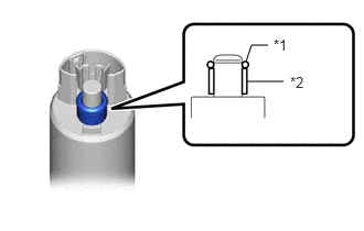
| *1 | O-ring |
| *2 | Fuel Pump Spacer |
Apply a light coat of gasoline to a new O-ring. Then install the O-ring and fuel pump spacer to the fuel pump.
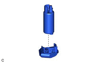
Install the fuel pump to the fuel pump filter.
23217D
2.INSTALL FUEL PUMP FILTER
Engage the 3 claws to install the fuel pump filter with the fuel pump to the fuel filter.
- NOTICE:
- ·
Make sure that the O-ring is not cut or pinched during the installation.
·Do not damage the fuel filter.
·Securely engage the claws.
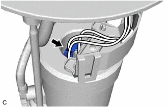
Connect the fuel pump harness connector to install the fuel pump harness to the fuel pump.
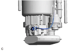
Engage the claw to connect the fuel pump harness to the fuel pump filter.
- NOTICE:
- ·
Securely engage the claw.
·Make sure that there is no foreign matter between the fuel pump and the ground terminal of the fuel pump harness.
·Make sure that the ground terminal of the fuel pump harness is securely connected to the fuel pump body.
Check the connection state of the fuel pump harness.
Measure the resistance according to the value(s) in the table below.
- Standard Resistance:
Tester Connection Condition Specified Condition Fuel pump body - Ground terminal of the fuel pump harness Always Below 1 Ω
If the result is not as specified, reconnect the fuel pump harness to the fuel pump filter so that the ground terminal of the fuel pump harness is securely connected to the fuel pump body.
77024A
3.INSTALL FUEL SUCTION PLATE SUB-ASSEMBLY
Engage the 2 claws to install the fuel filter to the No. 1 fuel sub-tank.
- NOTICE:
- ·
Do not apply excessive force to the tube or No. 1 fuel suction support.
·Securely engage the claws.
Install the spring to the fuel suction plate shaft and then install the fuel suction plate sub-assembly to the No. 1 fuel sub-tank.
Install a new E-ring to the fuel suction plate shaft.
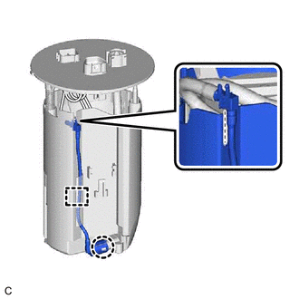
Engage the clamp and claw, and connect the fuel pump filter hose while aligning it with the installation position of the No. 1 fuel sub-tank.
- NOTICE:
-
Securely engage the clamp and claw.
Connect the 2 fuel pump harness connectors.
- NOTICE:
-
Make sure that the fuel pump harness connectors are connected securely.
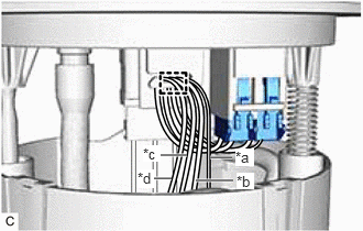
| *a | Black |
| *b | Red |
| *c | Blue |
| *d | Yellow |
Engage the clamp to connect the fuel pump harness to the fuel suction plate sub-assembly as shown in the illustration.
- NOTICE:
-
Make sure that the fuel pump harness has a moderate amount of slack.
83320
4.INSTALL FUEL SENDER GAUGE ASSEMBLY