RM3160E
_51
Engine / Hybrid System
_060159
2GR-FKS EMISSION CONTROL
_0299803
PURGE VALVE
A
2GR-FKS EMISSION CONTROL PURGE VALVE INSTALLATION
PROCEDURE

 25860
1.INSTALL PURGE VALVE (PURGE VSV)
a.
1.844,1.146 1.844,1.75
true
0.646,0.302 1.052,0.302
1.052,0.302 1.375,0.552
true
0.458,0.219 0.688,0.448
0.229,0.229
10
true
*1
1.781,1.792 2.063,1.99
0.281,0.198
10
true
*2
2.177,0.25 2.438,0.479
0.26,0.229
10
false
*a
2.688,0.24 2.917,0.448
0.229,0.208
10
false
*b
2.198,0.865 2.427,1.073
0.229,0.208
10
false
*c
2.844,0.458 3.073,0.656
0.229,0.198
10
false
*d
1.51,1.323 1.719,1.521
0.208,0.198
10
true
*a
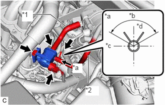
| *1 | No. 1 Fuel Vapor Feed Hose |
| *2 | Fuel Vapor Feed Hose Assembly |
| *a | View A |
| *b | Up |
| *c | Front |
| *d | 120° |
Install the purge valve (purge VSV) to the intake air surge tank assembly with the bolt.
- Torque:
- 21 N*m (214 kgf*cm, 15 ft.*lbf)
b.
Connect the No. 1 fuel vapor feed hose to the purge valve (purge VSV).
c.
Connect the fuel vapor feed hose assembly to the purge valve (purge VSV) and slide the clip to secure it.
- HINT:
-
Engage the clip within the area shown in the illustration.
d.
Connect the purge valve (purge VSV) connector.
11209
2.INSTALL V-BANK COVER SUB-ASSEMBLY