PRE-COLLISION PRE-COLLISION SYSTEM C1A4B Stop Light Relay Circuit
DESCRIPTION
The skid control ECU (brake actuator assembly) sends a stop light operation request signal to the stop light relay (stop light switch assembly). If the skid control ECU (brake actuator assembly) detects a malfunction in the stop light relay circuit, the driving support ECU assembly stores DTC C1A4B.
| DTC No. | Detection Item | DTC Detection Condition | Trouble Area |
|---|---|---|---|
| C1A4B | Stop Light Relay Circuit | Both of the following conditions are met:
1.
All of the following conditions are met: -
3 seconds have elapsed since the engine switch was turned to ON. -
The battery voltage is 10 V or more for 3 seconds or more. 2.
All of the following conditions are met for 1 second or more: -
Communication between the driving support ECU assembly and skid control ECU (brake actuator assembly) is normal. -
The driving support ECU assembly receives a stop light relay circuit malfunction signal from the skid control ECU (brake actuator assembly)
|
·
Skid control ECU (Brake actuator assembly) ·
Stop light relay (Stop light switch assembly) ·
Rear combination light assembly LH ·
Rear combination light assembly RH ·
Center stop light assembly ·
Rear light assembly LH ·
Rear light assembly RH ·
ECM ·
Certification ECU (Smart key ECU assembly) ·
Shift lock control ECU (Transmission floor shift assembly) ·
Harness or connector |
WIRING DIAGRAM
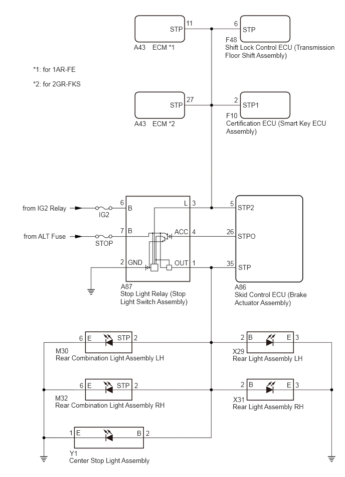
CAUTION / NOTICE / HINT
- NOTICE:
-
Inspect the fuses for circuits related to this system before performing the following procedure.
PROCEDURE
Turn the engine switch off.
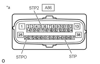
| *a | Front view of wire harness connector
(to Skid Control ECU (Brake Actuator Assembly)) |
Disconnect the A86 skid control ECU (brake actuator assembly) connector.
Measure the voltage according to the value(s) in the table below.
- Standard Voltage:
Tester Connection Condition Specified Condition A86-5 (STP2) - Body ground Brake pedal depressed 11 to 14 V Brake pedal released Below 1.5 V A86-26 (STPO) - Body ground Engine switch ON 11 to 14 V A86-35 (STP) - Body ground Brake pedal depressed 11 to 14 V Brake pedal released Below 1.5 V
Connect the A86 skid control ECU (brake actuator assembly) connector.
- Result:
Result Proceed to The voltage is as specified for every terminal. A Only the voltage at terminal STP2 is not as specified. B Only the voltage at terminal STPO is not as specified. C Only the voltage at terminal STP is not as specified. D The voltage at both terminal STPO and terminal STP are not as specified. E
A
B
C
D
E
Turn the engine switch off.
According to the display on the GTS, perform the Active Test Stop Light Relay.
- Chassis > ABS/VSC/TRC > Active Test
-
Tester Display Measurement Item Control Range Diagnostic Note Stop Light Relay Stop light relay (Stop light switch assembly) ON / OFF Test possible at vehicle speed of 0 km/h (0 mph)
- Chassis > ABS/VSC/TRC > Active Test
-
Tester Display Stop Light Relay - 50004 105 5
- OK:
The stop lights turn on and off correctly in response to the operation of the Active Test.
- Result:
Proceed to OK NG
OK
NG
Clear the DTCs.
Click hereVehicle Interior>PRE-COLLISION>PRE-COLLISION SYSTEM>DTC CHECK / CLEAR
- Body Electrical > Pre-Collision 2 > Clear DTCs
- 50002 220
According to the display on the GTS, perform the Active Test Stop Light Relay.
- Chassis > ABS/VSC/TRC > Active Test
-
Tester Display Measurement Item Control Range Diagnostic Note Stop Light Relay Stop light relay (Stop light switch assembly) ON / OFF Test possible at vehicle speed of 0 km/h (0 mph)
- Chassis > ABS/VSC/TRC > Active Test
-
Tester Display Stop Light Relay - 50004 105 5
Check for DTCs.
Click hereVehicle Interior>PRE-COLLISION>PRE-COLLISION SYSTEM>DTC CHECK / CLEAR
- Body Electrical > Pre-Collision 2 > Trouble Codes
- 50001 220
- OK:
DTC C1A4B is not output.
- Result:
Proceed to OK NG
OK
Click hereGeneral>INTRODUCTION>HOW TO TROUBLESHOOT ECU CONTROLLED SYSTEMS>HOW TO PROCEED WITH TROUBLESHOOTING
NG
According to the display on the GTS, perform the Active Test Stop Light Relay.
- Chassis > ABS/VSC/TRC > Active Test
-
Tester Display Measurement Item Control Range Diagnostic Note Stop Light Relay Stop light relay (Stop light switch assembly) ON / OFF Test possible at vehicle speed of 0 km/h (0 mph)
- Chassis > ABS/VSC/TRC > Active Test
-
Tester Display Stop Light Relay - 50004 105 5
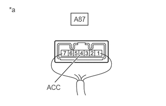
| *a | Component with harness connected
(Stop light relay (stop light switch assembly)) |
Measure the voltage according to the value(s) in the table below.
- HINT:
-
Do not disconnect the stop light relay (stop light switch assembly) connector.
- Standard Voltage:
Tester Connection Condition Specified Condition A87-4 (ACC) - Body ground Engine switch on (IG)
(Active test ON)Below 1.5 V
- Result:
Proceed to OK NG
OK
NG
Turn the engine switch off.
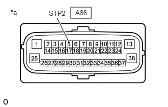
| *a | Front view of wire harness connector
(to Skid Control ECU (Brake Actuator Assembly)) |
Disconnect the A86 skid control ECU (brake actuator assembly) connector.
Measure the voltage according to the value(s) in the table below.
- Standard Voltage:
Tester Connection Condition Specified Condition A86-5 (STP2) - Body ground Brake pedal released Below 1.5 V
Connect the A86 skid control ECU (brake actuator assembly) connector.
- Result:
Proceed to OK NG
OK
NG
Turn the engine switch off.
Disconnect the A86 skid control ECU (brake actuator assembly) connector.
Disconnect the A43 ECM connector.
Measure the voltage according to the value(s) in the table below.
for 1AR-FE:
- Standard Voltage:
Tester Connection Condition Specified Condition A86-5 (STP2) or A43-11 (STP) - Body ground Brake pedal depressed 11 to 14 V
for 2GR-FKS:
- Standard Voltage:
Tester Connection Condition Specified Condition A86-5 (STP2) or A43-27 (STP) - Body ground Brake pedal depressed 11 to 14 V
Connect the A43 ECM connector.
Connect the A86 skid control ECU (brake actuator assembly) connector.
- Result:
Proceed to OK NG
OK
for 1AR-FE: Click hereEngine / Hybrid System>1AR-FE ENGINE CONTROL>ECM>COMPONENTS
for 2GR-FKS: Click hereEngine / Hybrid System>2GR-FKS (ENGINE CONTROL)>ECM>COMPONENTS
NG
Turn the engine switch off.
Disconnect the A86 skid control ECU (brake actuator assembly) connector.
Disconnect the F48 shift lock control ECU (transmission floor shift assembly) connector.
Measure the voltage according to the value(s) in the table below.
- Standard Voltage:
Tester Connection Condition Specified Condition A86-5 (STP2) or F48-6 (STP) - Body ground Brake pedal depressed 11 to 14 V
Connect the F48 shift lock control ECU (transmission floor shift assembly) connector.
Connect the A86 skid control ECU (brake actuator assembly) connector.
- Result:
Proceed to OK NG
OK
for UA80E: Click hereDrivetrain>UA80E (AUTOMATIC TRANSMISSION / TRANSAXLE)>SHIFT LEVER>COMPONENTS
for UA80F: Click hereDrivetrain>UA80F (AUTOMATIC TRANSMISSION / TRANSAXLE)>SHIFT LEVER>COMPONENTS
for U760E: Click hereDrivetrain>U760E AUTOMATIC TRANSMISSION / TRANSAXLE>SHIFT LEVER>COMPONENTS
NG
Turn the engine switch off.
Disconnect the A86 skid control ECU (brake actuator assembly) connector.
Disconnect the F10 certification ECU (smart key ECU assembly) connector.
Measure the voltage according to the value(s) in the table below.
- Standard Voltage:
Tester Connection Condition Specified Condition A86-5 (STP2) or F10-2 (STP1) - Body ground Brake pedal depressed 11 to 14 V
Connect the F10 certification ECU (smart key ECU assembly) connector.
Connect the A86 skid control ECU (brake actuator assembly) connector.
- Result:
Proceed to OK NG
OK
NG
Turn the engine switch off.
Disconnect the A86 skid control ECU (brake actuator assembly) connector.
Disconnect the A87 stop light relay (stop light switch assembly) connector.
Measure the resistance according to the value(s) in the table below.
- Standard Resistance:
Tester Connection Condition Specified Condition A86-5 (STP2) - A87-3 (L) Always Below 1 Ω A86-5 (STP2) or A87-3 (L) - Body ground Always 10 kΩ or higher
Connect the A87 stop light relay (stop light switch assembly) connector.
Connect the A86 skid control ECU (brake actuator assembly) connector.
- Result:
Proceed to OK NG
OK
NG
Turn the engine switch off.
Disconnect the A86 skid control ECU (brake actuator assembly) connector.
Disconnect the A87 stop light relay (stop light switch assembly) connector.
Measure the voltage according to the value(s) in the table below.
- Standard Voltage:
Tester Connection Condition Specified Condition A86-5 (STP2) or A87-3 (L) - Body ground Brake pedal released Below 1.5 V
Connect the A87 stop light relay (stop light switch assembly) connector.
Connect the A86 skid control ECU (brake actuator assembly) connector.
- Result:
Proceed to OK NG
OK
NG
Turn the engine switch off.
Disconnect the A86 skid control ECU (brake actuator assembly) connector.
Disconnect the A43 ECM connector.
Measure the voltage according to the value(s) in the table below.
for 1AR-FE:
- Standard Voltage:
Tester Connection Condition Specified Condition A86-5 (STP2) or A43-11 (STP) - Body ground Brake pedal released Below 1.5 V
for 2GR-FKS:
- Standard Voltage:
Tester Connection Condition Specified Condition A86-5 (STP2) or A43-27 (STP) - Body ground Brake pedal released Below 1.5 V
Connect the A43 ECM connector.
Connect the A86 skid control ECU (brake actuator assembly) connector.
- Result:
Proceed to OK NG
OK
for 1AR-FE: Click hereEngine / Hybrid System>1AR-FE ENGINE CONTROL>ECM>COMPONENTS
for 2GR-FKS: Click hereEngine / Hybrid System>2GR-FKS (ENGINE CONTROL)>ECM>COMPONENTS
NG
Turn the engine switch off.
Disconnect the A86 skid control ECU (brake actuator assembly) connector.
Disconnect the F48 shift lock control ECU (transmission floor shift assembly) connector.
Measure the voltage according to the value(s) in the table below.
- Standard Voltage:
Tester Connection Condition Specified Condition A86-5 (STP2) or F48-6 (STP) - Body ground Brake pedal released Below 1.5 V
Connect the F48 shift lock control ECU (transmission floor shift assembly) connector.
Connect the A86 skid control ECU (brake actuator assembly) connector.
- Result:
Proceed to OK NG
OK
for UA80E: Click hereDrivetrain>UA80E (AUTOMATIC TRANSMISSION / TRANSAXLE)>SHIFT LEVER>COMPONENTS
for UA80F: Click hereDrivetrain>UA80F (AUTOMATIC TRANSMISSION / TRANSAXLE)>SHIFT LEVER>COMPONENTS
for U760E: Click hereDrivetrain>U760E AUTOMATIC TRANSMISSION / TRANSAXLE>SHIFT LEVER>COMPONENTS
NG
Turn the engine switch off.
Disconnect the A86 skid control ECU (brake actuator assembly) connector.
Disconnect the F10 certification ECU (smart key ECU assembly) connector.
Measure the voltage according to the value(s) in the table below.
- Standard Voltage:
Tester Connection Condition Specified Condition A86-5 (STP2) or F10-2 (STP1) - Body ground Brake pedal released Below 1.5 V
Connect the F10 certification ECU (smart key ECU assembly) connector.
Connect the A86 skid control ECU (brake actuator assembly) connector.
- Result:
Proceed to OK NG
OK
NG
Turn the engine switch off.
Disconnect the A86 skid control ECU (brake actuator assembly) connector.
Disconnect the A87 stop light relay (stop light switch assembly) connector.
Measure the resistance according to the value(s) in the table below.
- Standard Resistance:
Tester Connection Condition Specified Condition A86-26 (STPO) - A87-4 (ACC) Always Below 1 Ω
Connect the A87 stop light relay (stop light switch assembly) connector.
Connect the A86 skid control ECU (brake actuator assembly) connector.
- Result:
Proceed to OK NG
OK
NG
Turn the engine switch off.
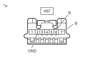
| *a | Front view of wire harness connector
(to Stop light relay (Stop light switch assembly)) |
Disconnect the A87 stop light relay (stop light switch assembly) connector.
Measure the voltage according to the value(s) in the table below.
- Standard Voltage:
Tester Connection Condition Specified Condition A87-6 (B) - Body ground Engine switch ON 11 to 14 V A87-7 (B) - Body ground Always 11 to 14 V
Measure the resistance according to the value(s) in the table below.
- Standard Resistance:
Tester Connection Condition Specified Condition A87-2 (GND) - Body ground Always Below 1 Ω
Connect the A87 stop light relay (stop light switch assembly) connector.
- Result:
Proceed to OK NG
OK
NG
Turn the engine switch off.
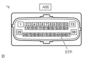
| *a | Front view of wire harness connector
(to Skid Control ECU (Brake Actuator Assembly)) |
Disconnect the A86 skid control ECU (brake actuator assembly) connector.
Measure the voltage according to the value(s) in the table below.
- Standard Voltage:
Tester Connection Condition Specified Condition A86-35 (STP) - Body ground Brake pedal released Below 1.5 V
Connect the A86 skid control ECU (brake actuator assembly) connector.
- Result:
Proceed to OK NG
OK
NG
Turn the engine switch off.
Disconnect the A86 skid control ECU (brake actuator assembly) connector.
Disconnect the M30 rear combination light assembly LH connector.
Measure the voltage according to the value(s) in the table below.
- Standard Voltage:
Tester Connection Condition Specified Condition A86-35 (STP) or M30-2 (STP) - Body ground Brake pedal depressed 11 to 14 V
Connect the M30 rear combination light assembly LH connector.
Connect the A86 skid control ECU (brake actuator assembly) connector.
- Result:
Proceed to OK NG
OK
NG
Turn the engine switch off.
Disconnect the A86 skid control ECU (brake actuator assembly) connector.
Disconnect the M32 rear combination light assembly RH connector.
Measure the voltage according to the value(s) in the table below.
- Standard Voltage:
Tester Connection Condition Specified Condition A86-35 (STP) or M32-2 (STP) - Body ground Brake pedal depressed 11 to 14 V
Connect the M32 rear combination light assembly RH connector.
Connect the A86 skid control ECU (brake actuator assembly) connector.
- Result:
Proceed to OK NG
OK
NG
Turn the engine switch off.
Disconnect the A86 skid control ECU (brake actuator assembly) connector.
Disconnect the Y1 center stop light assembly connector.
Measure the voltage according to the value(s) in the table below.
- Standard Voltage:
Tester Connection Condition Specified Condition A86-35 (STP) or Y1-2 (B) - Body ground Brake pedal depressed 11 to 14 V
Connect the Y1 center stop light assembly connector.
Connect the A86 skid control ECU (brake actuator assembly) connector.
- Result:
Proceed to OK NG
OK
NG
Turn the engine switch off.
Disconnect the A86 skid control ECU (brake actuator assembly) connector.
Disconnect the X29 rear light assembly LH connector.
Measure the voltage according to the value(s) in the table below.
- Standard Voltage:
Tester Connection Condition Specified Condition A86-35 (STP) or X29-2 (B) - Body ground Brake pedal depressed 11 to 14 V
Connect the X29 rear light assembly LH connector.
Connect the A86 skid control ECU (brake actuator assembly) connector.
- Result:
Proceed to OK NG
OK
NG
Turn the engine switch off.
Disconnect the A86 skid control ECU (brake actuator assembly) connector.
Disconnect the X31 rear light assembly RH connector.
Measure the voltage according to the value(s) in the table below.
- Standard Voltage:
Tester Connection Condition Specified Condition A86-35 (STP) or X31-2 (B) - Body ground Brake pedal depressed 11 to 14 V
Connect the X31 rear light assembly RH connector.
Connect the A86 skid control ECU (brake actuator assembly) connector.
- Result:
Proceed to OK NG
OK
NG
Turn the engine switch off.
Disconnect the A86 skid control ECU (brake actuator assembly) connector.
Disconnect the A87 stop light relay (stop light switch assembly) connector.
Measure the resistance according to the value(s) in the table below.
- Standard Resistance:
Tester Connection Condition Specified Condition A86-35 (STP) - A87-1 (OUT) Always Below 1 Ω A86-35 (STP) or A87-1 (OUT) - Body ground Always 10 kΩ or higher
Connect the A87 stop light relay (stop light switch assembly) connector.
Connect the A86 skid control ECU (brake actuator assembly) connector.
- Result:
Proceed to OK NG
OK
NG
Turn the engine switch off.
Disconnect the A86 skid control ECU (brake actuator assembly) connector.
Disconnect the A87 stop light relay (stop light switch assembly) connector.
Measure the voltage according to the value(s) in the table below.
- Standard Voltage:
Tester Connection Condition Specified Condition A86-35 (STP) or A87-1 (OUT) - Body ground Brake pedal released Below 1.5 V
Connect the A87 stop light relay (stop light switch assembly) connector.
Connect the A86 skid control ECU (brake actuator assembly) connector.
- Result:
Proceed to OK NG
OK
NG
Turn the engine switch off.
Disconnect the A86 skid control ECU (brake actuator assembly) connector.
Disconnect the M30 rear combination light assembly LH connector.
Measure the voltage according to the value(s) in the table below.
- Standard Voltage:
Tester Connection Condition Specified Condition A86-35 (STP) or M30-2 (STP) - Body ground Brake pedal released Below 1.5 V
Connect the M30 rear combination light assembly LH connector.
Connect the A86 skid control ECU (brake actuator assembly) connector.
- Result:
Proceed to OK NG
OK
NG
Turn the engine switch off.
Disconnect the A86 skid control ECU (brake actuator assembly) connector.
Disconnect the M32 rear combination light assembly RH connector.
Measure the voltage according to the value(s) in the table below.
- Standard Voltage:
Tester Connection Condition Specified Condition A86-35 (STP) or M32-2 (STP) - Body ground Brake pedal released Below 1.5 V
Connect the M32 rear combination light assembly RH connector.
Connect the A86 skid control ECU (brake actuator assembly) connector.
- Result:
Proceed to OK NG
OK
NG
Turn the engine switch off.
Disconnect the A86 skid control ECU (brake actuator assembly) connector.
Disconnect the Y1 center stop light assembly connector.
Measure the voltage according to the value(s) in the table below.
- Standard Voltage:
Tester Connection Condition Specified Condition A86-35 (STP) or Y1-2 (B) - Body ground Brake pedal released Below 1.5 V
Connect the Y1 center stop light assembly connector.
Connect the A86 skid control ECU (brake actuator assembly) connector.
- Result:
Proceed to OK NG
OK
NG
Turn the engine switch off.
Disconnect the A86 skid control ECU (brake actuator assembly) connector.
Disconnect the X29 rear light assembly LH connector.
Measure the voltage according to the value(s) in the table below.
- Standard Voltage:
Tester Connection Condition Specified Condition A86-35 (STP) or X29-2 (B) - Body ground Brake pedal released Below 1.5 V
Connect the X29 rear light assembly LH connector.
Connect the A86 skid control ECU (brake actuator assembly) connector.
- Result:
Proceed to OK NG
OK
NG
Turn the engine switch off.
Disconnect the A86 skid control ECU (brake actuator assembly) connector.
Disconnect the X31 rear light assembly RH connector.
Measure the voltage according to the value(s) in the table below.
- Standard Voltage:
Tester Connection Condition Specified Condition A86-35 (STP) or X31-2 (B) - Body ground Brake pedal released Below 1.5 V
Connect the X31 rear light assembly RH connector.
Connect the A86 skid control ECU (brake actuator assembly) connector.
- Result:
Proceed to OK NG
OK
NG
Turn the engine switch off.
| *a | Front view of wire harness connector
(to Stop light relay (Stop light switch assembly)) |
Disconnect the A87 stop light relay (stop light switch assembly) connector.
Measure the voltage according to the value(s) in the table below.
- Standard Voltage:
Tester Connection Condition Specified Condition A87-6 (B) - Body ground Engine switch ON 11 to 14 V A87-7 (B) - Body ground Always 11 to 14 V
Measure the resistance according to the value(s) in the table below.
- Standard Resistance:
Tester Connection Condition Specified Condition A87-2 (GND) - Body ground Always Below 1 Ω
Connect the A87 stop light relay (stop light switch assembly) connector.
- Result:
Proceed to OK NG
OK
NG
Turn the engine switch off.
Disconnect the A86 skid control ECU (brake actuator assembly) connector.
Disconnect the A87 stop light relay (stop light switch assembly) connector.
Measure the resistance according to the value(s) in the table below.
- Standard Resistance:
Tester Connection Condition Specified Condition A86-26 (STPO) or A87-4 (ACC) - Body ground Always 10 kΩ or higher
Connect the A87 stop light relay (stop light switch assembly) connector.
Connect the A86 skid control ECU (brake actuator assembly) connector.
- Result:
Proceed to OK NG
OK
NG