EXTERIOR PANELS / TRIM FRONT BUMPER REASSEMBLY
PROCEDURE

 52142C
1.INSTALL FRONT BUMPER STAY LH
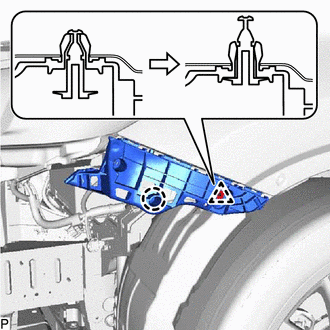
Engage the claw.
Engage the clip as shown in the illustration.
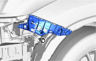
Install the front bumper stay LH with the bolt.
- Torque:
- 5.4 N*m (55 kgf*cm, 48 in.*lbf)
52141D
2.INSTALL FRONT BUMPER STAY RH
- HINT:
-
Use the same procedure as for the LH side.
52131A
3.INSTALL FRONT BUMPER REINFORCEMENT
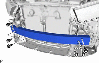
Install the front bumper reinforcement with the 6 bolts.
- Torque:
- 69 N*m (704 kgf*cm, 51 ft.*lbf)
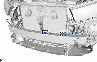
Engage the 2 clamps.
52611
4.INSTALL FRONT BUMPER ENERGY ABSORBER
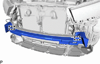
Engage the 2 guides to install the front bumper energy absorber.
75895K
5.INSTALL NO. 1 MOULDING TAPE
- HINT:
-
Use the same procedure for the RH side and LH side.
Clean the installation surface of the No. 1 moulding tape.
Remove any remaining double-sided tape from the front bumper cover.
- NOTICE:
- ·
If there is any foreign matter on the front bumper cover when the No. 1 moulding tape is installed, adhesion failure may occur.
·Do not use a screwdriver or other tool to remove the double-sided tape as the front bumper cover may be damaged, possibly leading to adhesion failure.
Wipe off any tape adhesive residue with cleaner.
Install a new No. 1 moulding tape.
- CAUTION:
- ·
Do not touch the heat light, as doing so may cause in burns.
·Touching heated parts for a long time may result in burns.
- HINT:
-
If the temperature of the No. 1 moulding tape or its installation surface on the front bumper cover is below 15°C (59°F), adhesion failure may occur. Use a heat light to heat the No. 1 moulding tape and its installation surface on the front bumper cover to the recommended temperature (15 to 40°C (59 to 104°F)).
Remove the release paper from the No. 1 moulding tape.
- HINT:
-
After removing the release paper, keep the exposed adhesive free from foreign matter.
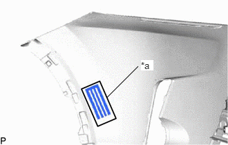
| *a | Line |
Install the No. 1 moulding tape to the front bumper cover as shown in the illustration.
- NOTICE:
-
If the No. 1 moulding tape has been removed, it must be replaced with a new one as it may be deformed or the strength of its adhesive may be deteriorated.
- HINT:
-
Make sure not to touch the exposed adhesive of the No. 1 moulding tape or the installation surface on the front bumper cover.
Using a squeegee, evenly press the No. 1 moulding tape to the front bumper cover with a force of 29 N (3 kgf, 6.5lbf) or more.
- HINT:
- ·
Make sure that the corners of the No. 1 moulding tape are not damaged or peeling off.
·After installing the No. 1 moulding tape, leave the front bumper cover in an area with an ambient temperature of 15°C (59°F) or more for 30 minutes or more to allow the adhesive to set.
Remove the protector sheet from the No. 1 moulding tape.
52129B
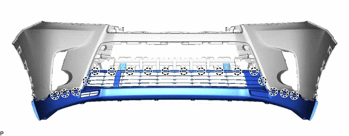
6.INSTALL LOWER FRONT BUMPER COVER
Engage the 18 claws.
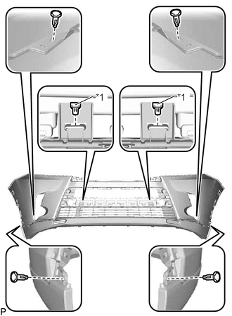
| *1 | Outside Moulding Retainer |
Install the 4 clips.
Install the 2 outside moulding retainers to install the lower front bumper cover.
52114A
7.INSTALL FRONT BUMPER EXTENSION MOUNTING BRACKET
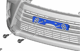
Engage the 4 claws.
Install the front bumper extension mounting bracket with the 2 screws.
53102A
8.INSTALL LOWER RADIATOR GRILLE SUB-ASSEMBLY
Engage the 16 claws.
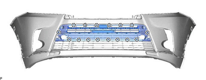
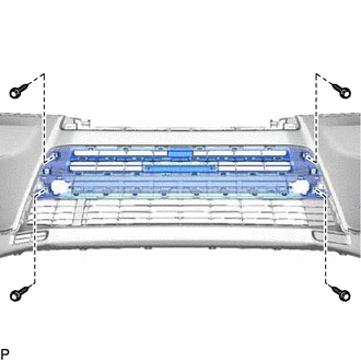
Install the lower radiator grille sub-assembly with the 4 screws.
53106D
9.INSTALL RADIATOR GRILLE GARNISH SUB-ASSEMBLY LH
Clean the lower radiator grille sub-assembly.
Remove any remaining double-sided tape from the lower radiator grille sub-assembly.
Wipe off any tape adhesive residue with cleaner.
Remove the release paper from a new radiator grille garnish sub-assembly LH.
- HINT:
-
After removing the release paper, keep the exposed adhesive free from foreign matter.
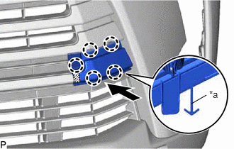
| *a | Hook |

|
Double-sided Tape |
Engage the hook.
Engage the 5 claws to install the radiator grille garnish sub-assembly LH as shown in the illustration.
53105D
10.INSTALL RADIATOR GRILLE GARNISH SUB-ASSEMBLY RH
- HINT:
-
Use the same procedure as for the LH side.
52521
11.INSTALL FRONT BUMPER UPPER CENTER RETAINER
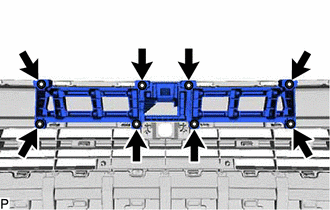
Install the front bumper upper center retainer with the 8 screws.
86790B
12.INSTALL FRONT TELEVISION CAMERA ASSEMBLY (w/ Panoramic View Monitor System)
52536
13.INSTALL FRONT BUMPER SIDE RETAINER LH
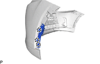
Engage the 3 claws.
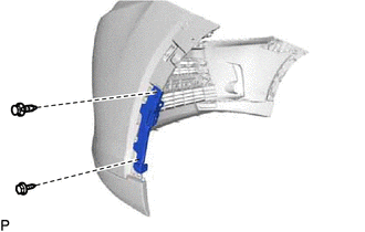
Install the clip.
Install the front bumper side retainer LH with the screw.
52535
14.INSTALL FRONT BUMPER SIDE RETAINER RH
- HINT:
-
Use the same procedure as for the LH side.
53879H
15.INSTALL FRONT FENDER LINER RETAINER
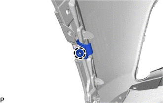
Engage the claw to install the front fender liner retainer.
- HINT:
-
Use the same procedure for the RH side and LH side.
81482C
16.INSTALL FOG LIGHT COVER LH
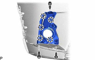
Engage the 5 claws.
Install the 2 clips.
Install the fog light cover LH with the screw.
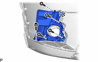
Engage the claw.
Install the clip.
Install the fog light mounting bracket LH with the 4 screws.
81481E
17.INSTALL FOG LIGHT COVER RH
- HINT:
-
Use the same procedure as for the LH side.
81220
18.INSTALL FOG LIGHT ASSEMBLY LH
81210A
19.INSTALL FOG LIGHT ASSEMBLY RH
- HINT:
-
Use the same procedure as for the LH side.
89347B
20.INSTALL FRONT CORNER ULTRASONIC SENSOR RETAINER (w/ TOYOTA Parking Assist-sensor System)
for 6 Sensor Type:
Click hereAudio / Visual / Telematics>PARK ASSIST / MONITORING>ULTRASONIC SENSOR(for Front Side)>INSTALLATION
89341K
21.INSTALL NO. 1 ULTRASONIC SENSOR (w/ TOYOTA Parking Assist-sensor System)
for 6 Sensor Type:
Click hereAudio / Visual / Telematics>PARK ASSIST / MONITORING>ULTRASONIC SENSOR(for Front Side)>INSTALLATION