Home › Vehicle Exterior › LIGHTING (EXT) › LIGHTING SYSTEM
RM37A0E _59 Vehicle Exterior _086888 LIGHTING (EXT) _0415934 LIGHTING SYSTEM J

LIGHTING (EXT)  LIGHTING SYSTEM  Door Mirror Foot Light Circuit  


DESCRIPTION

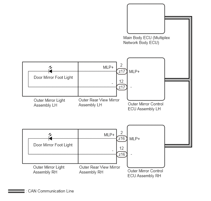
The outer mirror control ECU assembly receives signals from the main body ECU (multiplex network body ECU) to control the door mirror foot lights.

WIRING DIAGRAM
E433146E01
4.188,1.198 5.865,1.656 1.677,0.458 10 false Main Body ECU (Multiplex Network Body ECU) 4.344,3.458 5.615,4.01 1.271,0.552 10 false Outer Mirror Control ECU Assembly LH 4.333,5.74 5.604,6.292 1.271,0.552 10 false Outer Mirror Control ECU Assembly RH 4.385,2.354 4.865,2.625 0.479,0.271 10 false MLP+ 4.427,2.875 4.906,3.146 0.479,0.271 10 false - 4.396,4.646 4.875,4.917 0.479,0.271 10 false MLP+ 4.438,5.167 4.917,5.438 0.479,0.271 10 false - 3.5,2.208 3.979,2.479 0.479,0.271 10 false MLP+ 3.792,2.75 4.271,3.021 0.479,0.271 10 false - 3.531,4.51 4.01,4.781 0.479,0.271 10 false MLP+ 3.802,5.042 4.281,5.313 0.479,0.271 10 false - 0.875,6.427 2.667,6.719 1.792,0.292 10 false : CAN Communication Line 2.667,3.323 4.094,3.885 1.427,0.563 10 false Outer Rear View Mirror Assembly LH 2.688,5.615 4.115,6.177 1.427,0.563 10 false Outer Rear View Mirror Assembly RH 4.031,2.344 4.385,2.542 0.354,0.198 10 false z17 4.031,2.885 4.385,3.083 0.354,0.198 10 false z17 4.021,4.635 4.375,4.833 0.354,0.198 10 false z16 4.031,5.177 4.385,5.375 0.354,0.198 10 false z16 4.083,2.135 4.438,2.333 0.354,0.198 10 false 2 4.042,2.688 4.396,2.885 0.354,0.198 10 false 12 4.094,4.438 4.448,4.635 0.354,0.198 10 false 2 4.052,4.969 4.406,5.167 0.354,0.198 10 false 12 1.125,5.615 2.198,6.083 1.073,0.469 10 false Outer Mirror Light Assembly RH 1.146,3.333 2.229,3.76 1.083,0.427 10 false Outer Mirror Light Assembly LH 1.146,2.552 2.552,2.823 1.406,0.271 10 false Door Mirror Foot Light 1.135,4.854 2.542,5.125 1.406,0.271 10 false Door Mirror Foot Light

CAUTION / NOTICE / HINT

NOTICE:

If the main body ECU (multiplex network body ECU) is replaced, refer to Service Bulletin.


PROCEDURE

1.PERFORM ACTIVE TEST USING GTS
a.

Perform the Active Test according to the display on the GTS.

Body Electrical > Mirror L > Active Test
Tester Display Measurement Item Control Range Diagnostic Note
Foot Light Door mirror foot light LH OFF or ON -
Body Electrical > Mirror R > Active Test
Tester Display Measurement Item Control Range Diagnostic Note
Foot Light Door mirror foot light RH OFF or ON -
Body Electrical > Mirror L > Active Test
Tester Display
Foot Light
50004 225 1
Body Electrical > Mirror R > Active Test
Tester Display
Foot Light
50004 224 1
OK:

Door mirror foot lights illuminate.


Result:
Result Proceed to
OK A
NG (Door mirror foot light LH does not illuminate) B
NG (Door mirror foot light RH does not illuminate) C


A

PROCEED TO NEXT SUSPECTED AREA SHOWN IN PROBLEM SYMPTOMS TABLE

B

2.INSPECT OUTER REAR VIEW MIRROR ASSEMBLY LH

C

4.INSPECT OUTER REAR VIEW MIRROR ASSEMBLY RH
2.INSPECT OUTER REAR VIEW MIRROR ASSEMBLY LH
a.
E182505C05
1.385,1.375 0.75,1.01 false 1.688,1.583 1.844,1.833 false 0.115,0.083 0.313,0.26 0.198,0.177 10 false *a 0.354,0.906 0.833,1.281 0.479,0.375 10 false MLP+ 1.844,1.865 1.979,2.063 0.135,0.198 10 false -
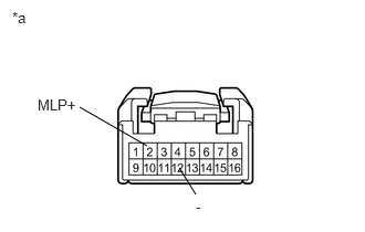
*a Component without harness connected
(Outer Rear View Mirror Assembly LH)


Remove the outer rear view mirror assembly LH.

Click hereVehicle Exterior>MIRROR (EXT)>OUTER REAR VIEW MIRROR>REMOVAL


b.

Connect a positive (+) lead from the auxiliary battery to terminal 2 (MLP+).


c.

Connect a negative (-) lead from the auxiliary battery to terminal 12 (-).


d.

Check that the door mirror foot light LH illuminates.

OK:

Door mirror foot light illuminates.


Result:
Proceed to
OK
NG


OK

REPLACE OUTER MIRROR CONTROL ECU ASSEMBLY LH

NG

3.INSPECT OUTER MIRROR LIGHT ASSEMBLY LH

OK

REPLACE OUTER REAR VIEW MIRROR ASSEMBLY LH

NG

REPLACE OUTER MIRROR LIGHT ASSEMBLY LH

4.INSPECT OUTER REAR VIEW MIRROR ASSEMBLY RH
a.
E182505C05
1.385,1.375 0.75,1.01 false 1.688,1.583 1.844,1.833 false 0.115,0.083 0.313,0.26 0.198,0.177 10 false *a 0.354,0.906 0.833,1.281 0.479,0.375 10 false MLP+ 1.844,1.865 1.979,2.063 0.135,0.198 10 false -
*a Component without harness connected
(Outer Rear View Mirror Assembly RH)


Remove the outer rear view mirror assembly RH.

Click hereVehicle Exterior>MIRROR (EXT)>OUTER REAR VIEW MIRROR>REMOVAL


b.

Connect a positive (+) lead from the auxiliary battery to terminal 2 (MLP+).


c.

Connect a negative (-) lead from the auxiliary battery to terminal 12 (-).


d.

Check that the door mirror foot light RH illuminates.

OK:

Door mirror foot light illuminates.


Result:
Proceed to
OK
NG


OK

REPLACE OUTER MIRROR CONTROL ECU ASSEMBLY RH

NG

5.INSPECT OUTER MIRROR LIGHT ASSEMBLY RH

OK

REPLACE OUTER REAR VIEW MIRROR ASSEMBLY RH

NG

REPLACE OUTER MIRROR LIGHT ASSEMBLY RH