LIGHTING (EXT) SWITCH HOUSING REMOVAL
CAUTION / NOTICE / HINT
The necessary procedures (adjustment, calibration, initialization or registration) that must be performed after parts are removed and installed, or replaced during steering wheel switch housing removal/installation are shown below.
| Replaced Part or Performed Procedure | Necessary Procedure | Effect/Inoperative Function when Necessary Procedure not Performed | Link |
|---|---|---|---|
|
*1: Learning can also be performed using the GTS. Click here( |
|||
| Disconnect cable from negative auxiliary battery terminal | Perform steering sensor zero point calibration | Lane Control System | ( ) |
| Parking Support Brake System*1 | |||
| Pre-collision System | |||
| Memorize steering angle neutral point | Parking Assist Monitor System | ()
|
|
| Panoramic View Monitor System | ()
|
||
| Initialize back door lock | Power Door Lock Control System | ()
|
|
| Reset back door close position | Power Back Door System | ()
|
|
| Removal/installation of the spiral cable with sensor sub-assembly | Steering angle setting | Parking Assist Monitor System | ()
|
| Adjust steering angle | Panoramic View Monitor System | ()
|
|
| Steering angle neutral point | Parking Assist Monitor System | ()
|
|
| Parking Support Brake System | ()
|
||
| Panoramic View Monitor System | ()
|
||
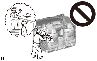
- CAUTION:
-
-
Some of these service operations affect the SRS airbag system. Read the precautionary notices concerning the SRS airbag system before servicing.
-
Click hereVehicle Interior>SUPPLEMENTAL RESTRAINT SYSTEMS>AIRBAG SYSTEM>PRECAUTION
- NOTICE:
-
After the ignition switch is turned off, the radio and display receiver assembly or the radio receiver assembly records various types of memory and settings. As a result, after turning the ignition switch off, make sure to wait at least 120 seconds before disconnecting the cable from the negative (-) auxiliary battery terminal.
| Replaced Part or Performed Procedure | Necessary Procedure | Effect/Inoperative Function when Necessary Procedure not Performed | Link |
|---|---|---|---|
|
*1: Learning can also be performed using the GTS. Click here( |
|||
| Disconnect cable from negative auxiliary battery terminal | Perform steering sensor zero point calibration | Lane Control System | ()
|
| Parking Support Brake System*1 | |||
| Pre-collision System | |||
| Memorize steering angle neutral point | Parking Assist Monitor System | ()
|
|
| Panoramic View Monitor System | ()
|
||
| Initialize back door lock | Power Door Lock Control System | ()
|
|
| Reset back door close position | Power Back Door System | ()
|
|
| Removal/installation of the spiral cable with sensor sub-assembly | Steering angle setting | Parking Assist Monitor System | ()
|
| Adjust steering angle | Panoramic View Monitor System | ()
|
|
| Steering angle neutral point | Parking Assist Monitor System | ()
|
|
| Parking Support Brake System | ()
|
||
| Panoramic View Monitor System | ()
|
||
- CAUTION:
-
-
Some of these service operations affect the SRS airbag system. Read the precautionary notices concerning the SRS airbag system before servicing.
-
Click hereVehicle Interior>SUPPLEMENTAL RESTRAINT SYSTEMS>AIRBAG SYSTEM>PRECAUTION
- NOTICE:
-
After the ignition switch is turned off, the radio and display receiver assembly or the radio receiver assembly records various types of memory and settings. As a result, after turning the ignition switch off, make sure to wait at least 120 seconds before disconnecting the cable from the negative (-) auxiliary battery terminal.
PROCEDURE

 1.REMOVE SPIRAL CABLE WITH SENSOR SUB-ASSEMBLY
84650
2.REMOVE WINDSHIELD WIPER SWITCH ASSEMBLY
84329
3.REMOVE TURN SIGNAL SWITCH
84319
4.REMOVE STEERING WHEEL SWITCH HOUSING
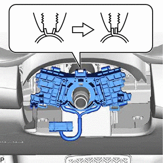
Using pliers, expand the clamp as shown in the illustration.
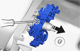
| *a | Protective Tape |

|
Remove in this Direction |
While holding the clamp expanded, using a screwdriver with its tip wrapped with protective tape, disengage the claw and remove the steering wheel switch housing as shown in the illustration.