METER / GAUGE / DISPLAY HEADUP DISPLAY SYSTEM B132187 Lost Communication with EMV Missing Message
DESCRIPTION
After the meter mirror sub-assembly has started, the meter mirror sub-assembly attempts to detect the radio and display receiver assembly by performing communication via local bus.
This DTC is stored when the radio and display receiver assembly has been detected but communication between the meter mirror sub-assembly and radio and display receiver assembly is interrupted.
| DTC No. | Detection Item | DTC Detection Condition | Trouble Area |
|---|---|---|---|
| B132187 | Lost Communication with EMV Missing Message | Diagnosis Condition:
·
The meter mirror sub-assembly has started ·
The radio and display receiver assembly has started Malfunction Status: After the radio and display receiver assembly is detected, communication via local bus is interrupted Malfunction Time: 30 seconds or more |
·
Radio and display receiver assembly ·
Harness or connector ·
Meter mirror sub-assembly |
WIRING DIAGRAM
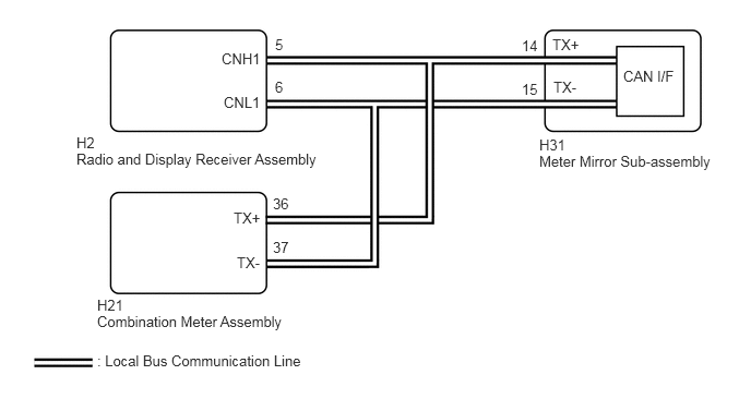
PROCEDURE
Check if navigation system DTCs are output.
- Body Electrical > Navigation System > Trouble Codes
- 50001 212
- Result:
Result Proceed to DTCs are not output A DTCs are output B
A
B
Check if meter / gauge system DTCs are output.
- Body Electrical > Combination Meter > Trouble Codes
- 50001 122
- HINT:
- ·
If DTC B132187 is output from the headup display system and is not output from the meter / gauge system, it can be suspected that the meter mirror sub-assembly has an internal malfunction.
·If DTC B132187 is output from the meter / gauge system and is not output from the navigation system, it can be suspected that the radio and display receiver assembly has an internal malfunction.
- Result:
Result Proceed to DTC B132187 is not output A DTC B132187 is output B
A
B