A25A-FXS, A25B-FXS FUEL FUEL SENDER GAUGE ASSEMBLY REMOVAL
CAUTION / NOTICE / HINT
The necessary procedures (adjustment, calibration, initialization or registration) that must be performed after parts are removed and installed, or replaced during fuel sender gauge assembly removal/installation are shown below.
| Replaced Part or Performed Procedure | Necessary Procedure | Effect/Inoperative Function when Necessary Procedure not Performed | Link |
|---|---|---|---|
|
*1: Learning can also be performed using the GTS. Click here( |
|||
| Auxiliary battery terminal is disconnected/reconnected | Perform steering sensor zero point calibration | Lane Control System | ( ) |
| Parking Support Brake System*1 | |||
| Pre-collision System | |||
| Memorize steering angle neutral point | Parking Assist Monitor System | ()
|
|
| Panoramic View Monitor System | ()
|
||
| Initialize back door lock | Power Door Lock Control System | ()
|
|
| Reset back door close position | Power Back Door System | ()
|
|
- CAUTION:
- ·
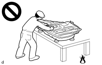
Never perform work on fuel system components near any possible ignition sources.
·Vaporized fuel could ignite, resulting in a serious accident.
·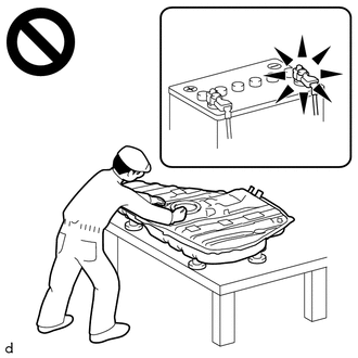
Do not perform work on fuel system components without first disconnecting the cable from the negative (-) auxiliary battery terminal.
·Sparks could cause vaporized fuel to ignite, resulting in a serious accident.
- NOTICE:
-
After the ignition switch is turned off, the radio and display receiver assembly or the radio receiver assembly records various types of memory and settings. As a result, after turning the ignition switch off, make sure to wait at least 120 seconds before disconnecting the cable from the negative (-) auxiliary battery terminal.
PROCEDURE

 77020A
1.REMOVE FUEL SUCTION TUBE WITH PUMP AND GAUGE ASSEMBLY
83320
2.REMOVE FUEL SENDER GAUGE ASSEMBLY
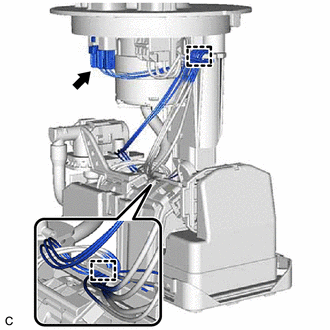
Disconnect the fuel sender gauge assembly connector.
Disengage the 2 clamps to disconnect the wire harness from the fuel suction tube with pump and gauge assembly.
- NOTICE:
- ·
Do not damage the wire harness.
·When disengaging each wire harness from the clamp, disengage one wire at a time.
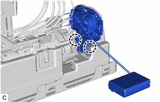
Disengage the 2 claws to remove the fuel gauge bracket with fuel sender gauge assembly from the fuel suction tube with pump and gauge assembly.
- NOTICE:
-
Be careful not to bend the arm of the fuel sender gauge assembly.
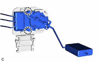
Disengage the 2 claws to remove the fuel sender gauge assembly from the fuel gauge bracket.