AUDIO / VIDEO RADIO ANTENNA CORD INSTALLATION
PROCEDURE

 86101Q
1.INSTALL NO. 4 ANTENNA CORD SUB-ASSEMBLY
Engage each clamp to install the No. 4 antenna cord sub-assembly.
Connect the connector.
86101D
2.INSTALL NO. 3 ANTENNA CORD SUB-ASSEMBLY (for Normal Roof)
- HINT:
-
Butyl tape and adhesive tape are not available as supply parts. If these pieces of tape still have enough adhesion to secure the No. 3 antenna cord sub-assembly to the roof headlining assembly, reuse them. If the adhesive tape and/or the butyl tape is no longer sticky, apply new tape following the procedure below.
Apply new butyl tape.
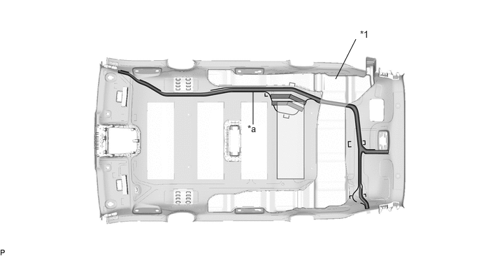
| *1 | Rear Roof Air Duct | - | - |
| *a | Marking | - | - |

|
Butyl tape | - | - |
Remove the old butyl tape from the roof headlining assembly.
Prepare an appropriate amount of new butyl tape.
- HINT:
-
Be careful not to touch the adhesive surface.
Apply the butyl tape to the roof headlining assembly while aligning the tape with the markings on the roof headlining assembly.
- HINT:
-
Slide the butyl tape under the rear roof air duct then press it to attach it.
Peel off the release paper from the butyl tape.
Align the marking tape (A) on the No. 3 antenna cord sub-assembly with the protrusion on the front of the roof headlining assembly and wrap tape around the No. 3 antenna cord sub-assembly and protrusion of the roof headlining assembly.
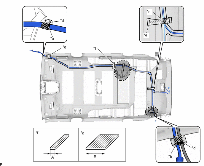
| *a | Marking Tape (A) | *b | Marking Tape (B) |
| *c | Marking Tape (C) | *d | Protrusion |
| *e | Marking | *f | Adhesive Tape Size (A) |
| *g | Adhesive Tape Size (B) | - | - |

|
Adhesive Tape | 
|
Adjustment Area |
- Adhesive Tape Size:
Area Dimension Area Dimension A 20 mm (0.787 in.) B 80 mm (3.15 in.)
Using wire, pass the No. 3 antenna cord sub-assembly between the rear roof air duct and roof headlining assembly.
Secure the wire with a diameter of 2.0 mm (0.0787 in.) to the No. 3 antenna cord sub-assembly with vinyl tape as shown in the illustration.
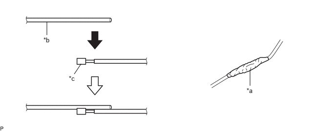
| *a | Vinyl Tape | *b | Wire |
| *c | Connector | - | - |
- NOTICE:
-
Make sure that the wire is secured with vinyl tape to prevent the wire from separating from the No. 3 antenna cord sub-assembly when removing it.
- HINT:
-
As the No. 3 antenna cord sub-assembly is likely to be caught in the narrow areas inside the roof headlining assembly, make sure to align in a straight line and cover the edges of the connectors with vinyl tape.
Align the marking tape (B) on the No. 3 antenna cord sub-assembly with the protrusion on the rear of the roof headlining assembly and wrap tape around the No. 3 antenna cord sub-assembly and protrusion of the roof headlining assembly.
Align the marking tape (C) on the No. 3 antenna cord sub-assembly with the marking on the roof headlining assembly and secure the No. 3 antenna cord sub-assembly with the adhesive tape as shown in the illustration.
Install the No. 3 antenna cord sub-assembly to the roof headlining assembly.
- NOTICE:
- ·
Make sure that there are no gaps between the roof headlining assembly and No. 3 antenna cord sub-assembly, and that the No. 3 antenna cord sub-assembly is not twisted.
·Make sure the No. 3 antenna cord assembly is securely installed. If any part of the No. 3 antenna cord sub-assembly is loose, it will cause an abnormal noise.
- HINT:
-
Secure the extra length of the No. 3 antenna cord sub-assembly in the adjustment area.
Apply the adhesive tape as shown in the illustration to secure the No. 3 antenna cord sub-assembly.
86101D
3.INSTALL NO. 3 ANTENNA CORD SUB-ASSEMBLY (for Moon Roof)
- HINT:
-
Butyl tape and adhesive tape are not available as supply parts. If these pieces of tape still have enough adhesion to secure the No. 3 antenna cord sub-assembly to the roof headlining assembly, reuse them. If the adhesive tape and/or the butyl tape is no longer sticky, apply new tape following the procedure below.
Apply new butyl tape.
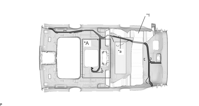
| *A | w/ Rear Seat Entertainment System | - | - |
| *1 | Rear Roof Air Duct | - | - |
| *a | Marking | - | - |
|
|
Butyl tape | - | - |
Remove the old butyl tape from the roof headlining assembly.
Prepare an appropriate amount of new butyl tape.
- HINT:
-
Be careful not to touch the adhesive surface.
Apply the butyl tape to the roof headlining assembly while aligning the tape with the markings on the roof headlining assembly.
- HINT:
-
Slide the butyl tape under the rear roof air duct then press it to attach it.
Peel off the release paper from the butyl tape.
Align the marking tape (A) on the No. 3 antenna cord sub-assembly with the protrusion on the front of the roof headlining assembly and wrap tape around the No. 3 antenna cord sub-assembly and protrusion of the roof headlining assembly.
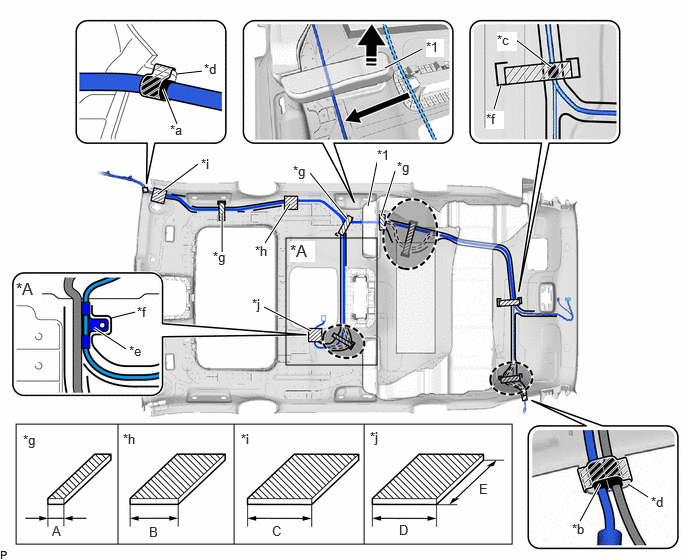
| *A | w/ Rear Seat Entertainment System | - | - |
| *1 | Rear Roof Air Duct | - | - |
| *a | Marking Tape (A) | *b | Marking Tape (B) |
| *c | Marking Tape (C) | *d | Protrusion |
| *e | Clamp | *f | Marking |
| *g | Adhesive Tape Size (A) | *h | Adhesive Tape Size (B) |
| *i | Adhesive Tape Size (C) | *j | Adhesive Tape Size (D) |

|
Lift up in this Direction |
|
Adjustment Area |
|
|
Adhesive Tape | - | - |
- Adhesive Tape Size:
Area Dimension Area Dimension A 20 mm (0.787 in.) B 60 mm (2.36 in.) C 80 mm (3.15 in.) D 80 mm (3.15 in.) E 100 mm (3.94 in.) - -
While lifting the rear roof air duct as shown in the illustration, pass the No. 3 antenna cord sub-assembly through.
- HINT:
-
Lift up the rear roof air duct to the extent that the No. 3 antenna cord sub-assembly can be passed through.
Using wire, pass the No. 3 antenna cord sub-assembly between the rear roof air duct and roof headlining assembly.
Secure the wire with a diameter of 2.0 mm (0.0787 in.) to the No. 3 antenna cord sub-assembly with vinyl tape as shown in the illustration.
| *a | Vinyl Tape | *b | Wire |
| *c | Connector | - | - |
- NOTICE:
-
Make sure that the wire is secured with vinyl tape to prevent the wire from separating from the No. 3 antenna cord sub-assembly when removing it.
- HINT:
-
As the No. 3 antenna cord sub-assembly is likely to be caught in the narrow areas inside the roof headlining assembly, make sure to align in a straight line and cover the edges of the connectors with vinyl tape.
Align the marking tape (B) on the No. 3 antenna cord sub-assembly with the protrusion on the rear of the roof headlining assembly and wrap tape around the No. 3 antenna cord sub-assembly and protrusion of the roof headlining assembly.
Align the marking tape (C) on the No. 3 antenna cord sub-assembly with the marking on the roof headlining assembly and secure the No. 3 antenna cord sub-assembly with the adhesive tape as shown in the illustration.
w/ Rear Seat Entertainment System:
Align the clamp on the No. 3 antenna cord sub-assembly with the marking on the roof headlining assembly.
Apply hot-melt glue, to secure the clamp on the No. 3 antenna cord sub-assembly as shown inthe illustration.
Install the No. 3 antenna cord sub-assembly to the roof headlining assembly.
- NOTICE:
- ·
Make sure that there are no gaps between the roof headlining assembly and No. 3 antenna cord sub-assembly, and that the No. 3 antenna cord sub-assembly is not twisted.
·Make sure the No. 3 antenna cord assembly is securely installed. If any part of the No. 3 antenna cord sub-assembly is loose, it will cause an abnormal noise.
- HINT:
-
Secure the extra length of the No. 3 antenna cord sub-assembly in the adjustment area.
Apply the adhesive tape as shown in the illustration to secure the No. 3 antenna cord sub-assembly.
86101D
4.INSTALL NO. 3 ANTENNA CORD SUB-ASSEMBLY (for Panoramic Moon Roof)
- HINT:
-
Butyl tape and adhesive tape are not available as supply parts. If these pieces of tape still have enough adhesion to secure the No. 3 antenna cord sub-assembly to the roof headlining assembly, reuse them. If the adhesive tape and/or the butyl tape is no longer sticky, apply new tape following the procedure below.
Apply new butyl tape.
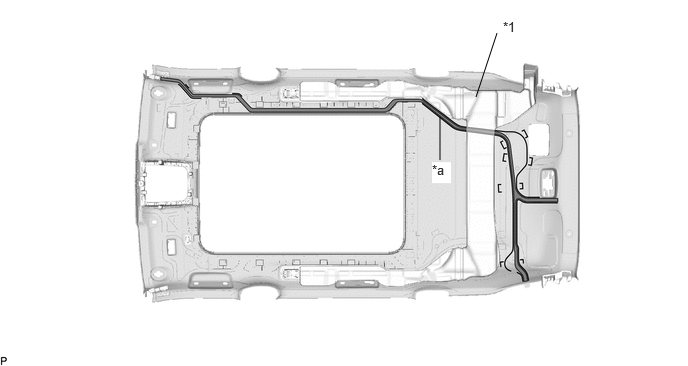
| *1 | Rear Roof Air Duct | - | - |
| *a | Marking | - | - |
|
|
Butyl tape | - | - |
Remove the old butyl tape from the roof headlining assembly.
Prepare an appropriate amount of new butyl tape.
- HINT:
-
Be careful not to touch the adhesive surface.
Apply the butyl tape to the roof headlining assembly while aligning the tape with the markings on the roof headlining assembly.
- HINT:
-
Slide the butyl tape under the rear roof air duct then press it to attach it.
Peel off the release paper from the butyl tape.
Align the marking tape (A) on the No. 3 antenna cord sub-assembly with the protrusion on the front of the roof headlining assembly and wrap tape around the No. 3 antenna cord sub-assembly and protrusion of the roof headlining assembly.
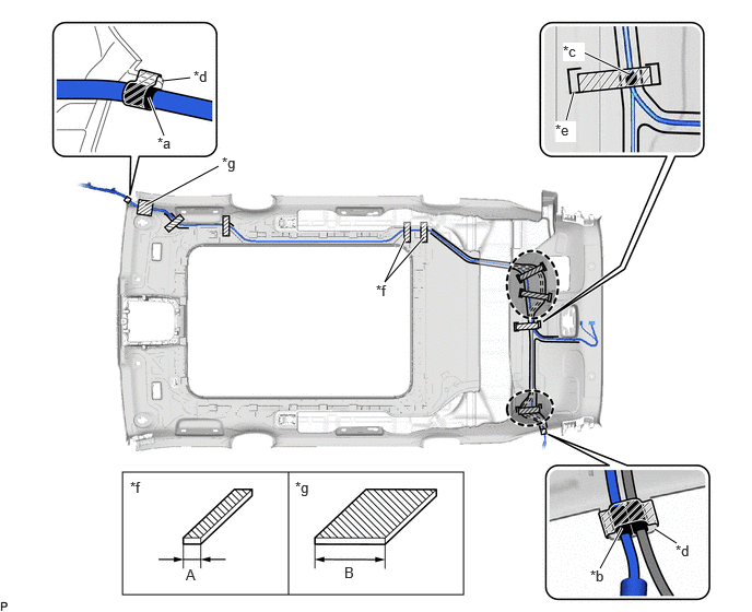
| *a | Marking Tape (A) | *b | Marking Tape (B) |
| *c | Marking Tape (C) | *d | Protrusion |
| *e | Marking | *f | Adhesive Tape Size (A) |
| *g | Adhesive Tape Size (B) | - | - |
|
|
Adhesive Tape |
|
Adjustment Area |
- Adhesive Tape Size:
Area Dimension Area Dimension A 20 mm (0.787 in.) B 80 mm (3.15 in.)
Using wire, pass the No. 3 antenna cord sub-assembly between the rear roof air duct and roof headlining assembly.
Secure the wire with a diameter of 2.0 mm (0.0787 in.) to the No. 3 antenna cord sub-assembly with vinyl tape as shown in the illustration.
| *a | Vinyl Tape | *b | Wire |
| *c | Connector | - | - |
- NOTICE:
-
Make sure that the wire is secured with vinyl tape to prevent the wire from separating from the No. 3 antenna cord sub-assembly when removing it.
- HINT:
-
As the No. 3 antenna cord sub-assembly is likely to be caught in the narrow areas inside the roof headlining assembly, make sure to align in a straight line and cover the edges of the connectors with vinyl tape.
Align the marking tape (B) on the No. 3 antenna cord sub-assembly with the protrusion on the rear of the roof headlining assembly and wrap tape around the No. 3 antenna cord sub-assembly and protrusion of the roof headlining assembly.
Align the marking tape (C) on the No. 3 antenna cord sub-assembly with the marking on the roof headlining assembly and secure the No. 3 antenna cord sub-assembly with the adhesive tape as shown in the illustration.
Install the No. 3 antenna cord sub-assembly to the roof headlining assembly.
- NOTICE:
- ·
Make sure that there are no gaps between the roof headlining assembly and No. 3 antenna cord sub-assembly, and that the No. 3 antenna cord sub-assembly is not twisted.
·Make sure the No. 3 antenna cord assembly is securely installed. If any part of the No. 3 antenna cord sub-assembly is loose, it will cause an abnormal noise.
- HINT:
-
Secure the extra length of the No. 3 antenna cord sub-assembly in the adjustment area.
Apply the adhesive tape as shown in the illustration to secure the No. 3 antenna cord sub-assembly.
5.INSTALL ROOF HEADLINING ASSEMBLY
86101
6.INSTALL ANTENNA CORD SUB-ASSEMBLY
Engage each clamp to install the antenna cord sub-assembly as shown in the illustration.
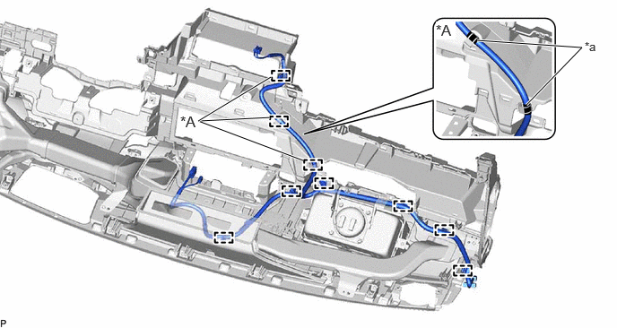
| *A | for Antenna Cord Sub-assembly with Branch Line | - | - |
| *a | Marking Tape | - | - |
w/ Antenna Divider:
Connect the connector.
86101J
7.INSTALL NO. 2 ANTENNA CORD SUB-ASSEMBLY (w/ Navigation Antenna)
for Antenna Cord Sub-assembly without Branch Line:
Engage each clamp to install the No. 2 antenna cord sub-assembly as shown in the illustration.
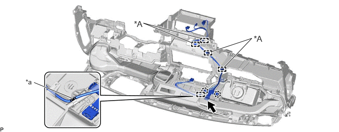
| *A | w/ Navigation ECU | - | - |
| *a | Marking Tape | - | - |
Engage the 2 claws and connect the connector.
for Antenna Cord Sub-assembly with Branch Line:
Engage each clamp to install the No. 2 antenna cord sub-assembly as shown in the illustration.
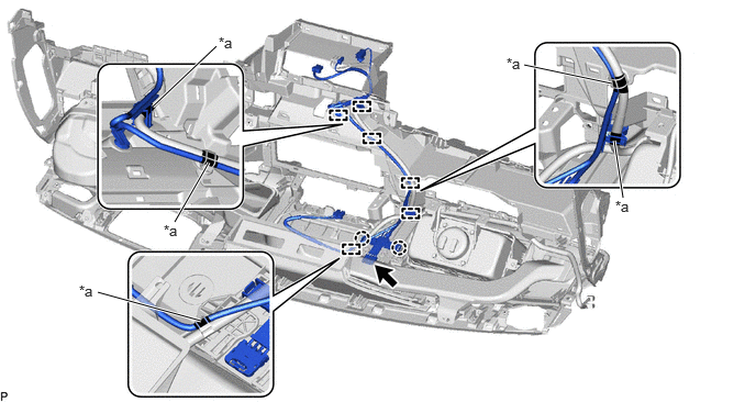
| *a | Marking Tape | - | - |
Engage the 2 claws and connect the connector.
55846A
8.INSTALL NO. 4 HEATER TO REGISTER DUCT
9.INSTALL INSTRUMENT PANEL SAFETY PAD SUB-ASSEMBLY