TELEMATICS COMMUNICATION TELEMATICS BOX REMOVAL
PROCEDURE

 81260A
1.REMOVE MAP LIGHT ASSEMBLY
867E1
2.REMOVE COMMUNICATION TELEMATICS BOX
- NOTICE:
- ·
Prevention of static electricity is required during this procedure.
·Use static electricity countermeasures SST (desktop anti-static mat set) and observe all precautions to prevent damage to the system by electrostatic discharge (ESD).
Click hereAudio / Visual / Telematics>TELEMATICS>COMMUNICATION TELEMATICS BOX>PRECAUTION
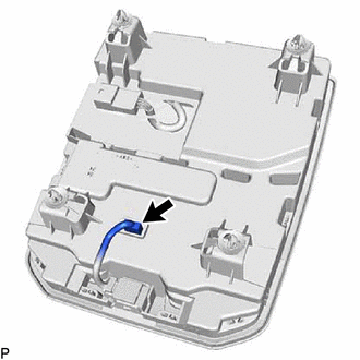
Disconnect the connector.
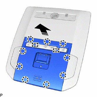

|
Remove in this Direction |
Disengage the 9 claws and 2 guides to remove the trim plate as shown in the illustration.
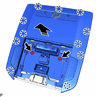
|
|
Remove in this Direction |
Using a T20 "TORX" socket wrench, remove the 2 screws.
Disengage the 11 claws to remove the map light bezel assembly with circuit plate assembly as shown in the illustration.
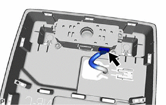
Disconnect the connector.
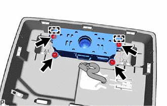
Using a T20 "TORX" socket wrench, remove the 4 screws.
Disengage the 2 guides to remove the communication telematics box.