UA80F AUTOMATIC TRANSMISSION / TRANSAXLE TRANSMISSION CONTROL CABLE ADJUSTMENT
CAUTION / NOTICE / HINT
- NOTICE:
-
Before adjusting the transmission control cable assembly, check that the park/neutral position switch assembly and shift lever are in N.
PROCEDURE

 1.REMOVE CONSOLE BOX ASSEMBLY
55446A
2.REMOVE NO. 1 SWITCH HOLE BASE
55606
3.REMOVE NO. 1 INSTRUMENT PANEL UNDER COVER SUB-ASSEMBLY
58816B
4.REMOVE FRONT CONSOLE BOX INSERT
5.ADJUST SHIFT LEVER POSITION
- NOTICE:
-
Before adjusting the transmission control cable assembly, check that the park/neutral position switch assembly and shift lever are in N.
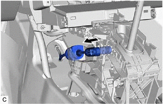
Disconnect the transmission control cable assembly from the transmission floor shift assembly.
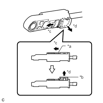
| *a | Slider |
| *b | Lock Piece |
| *c | Slide |
| *d | Pull |
Slide the slider of the transmission control cable assembly in the direction indicated by the arrow in the illustration and pull the lock piece outward.
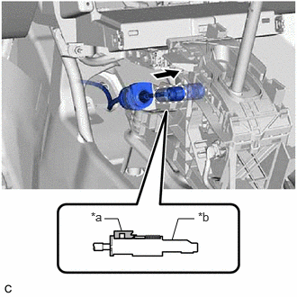
| *a | Lock Piece |
| *b | Adjuster Case |
Connect the transmission control cable assembly to the transmission floor shift assembly.
- NOTICE:
- ·
Check that the lock piece is pulled out.
·Push the end of the transmission control cable assembly all the way to the base of the transmission floor shift assembly pin.
·Connect the transmission control cable assembly so that the lock piece faces the driver side.
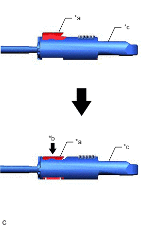
| *a | Lock Piece |
| *b | Push in |
| *c | Adjuster Case |
Push the lock piece into the adjuster case.
- NOTICE:
- ·
Check that the park/neutral position switch assembly and shift lever are in N.
·Securely push in the lock piece until the slider lock is engaged.
·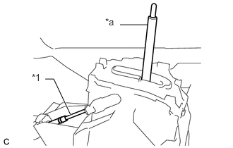 1.771,0.365 2.177,0.365 false 0.667,1.167 0.792,1.167 0.792,1.167 1.042,1.698 true 0.469,1.063 0.708,1.333 0.24,0.271 10 false *1 1.552,0.24 1.875,0.479 0.323,0.24 10 false *a
*1 Transmission Control Cable Assembly *a Lever Shaft
When pushing in the lock piece of the adjuster case to lock it, remove your hand from the lever shaft.
·When pushing in the lock piece of the adjuster case to lock it, do not move the lever shaft or transmission control cable assembly forward or backward.
After adjusting the shift lever position, check the position and operation of the shift lever. If there is a problem, adjust the shift lever position again.
58816B
6.INSTALL FRONT CONSOLE BOX INSERT
55606
7.INSTALL NO. 1 INSTRUMENT PANEL UNDER COVER SUB-ASSEMBLY
55446A
8.INSTALL NO. 1 SWITCH HOLE BASE
9.INSTALL CONSOLE BOX ASSEMBLY