Home › Audio / Visual / Telematics › NAVIGATION / MULTI INFO DISPLAY › NAVIGATION SYSTEM (for 8 Inch Display)
RM37A0E _56 Audio / Visual / Telematics _086878 NAVIGATION / MULTI INFO DISPLAY _0418790 NAVIGATION SYSTEM(for 8 Inch Display) C

NAVIGATION / MULTI INFO DISPLAY  NAVIGATION SYSTEM(for 8 Inch Display)  B153A  GVIF Disconnected (from Extension Module to H/U)  


DESCRIPTION

DTC No. Detection Item DTC Detection Condition Trouble Area
B153A GVIF Disconnected (from Extension Module to H/U) GVIF disconnected (from navigation ECU to radio and display receiver assembly)
·

Harness or connector

·

Navigation ECU

·

Radio and display receiver assembly


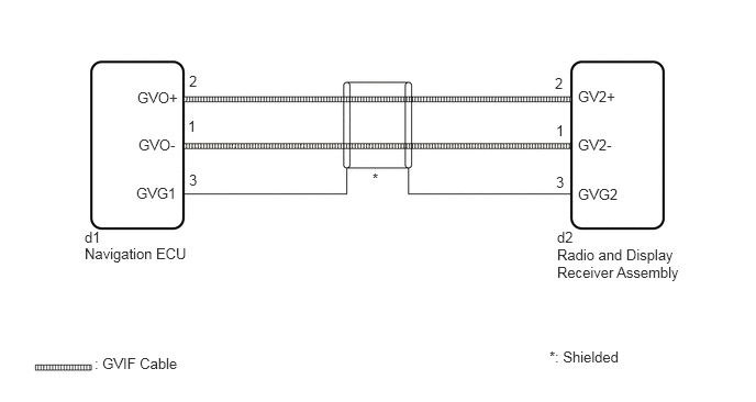
WIRING DIAGRAM

E393030E02
0.802,2.167 1.24,2.375 0.438,0.208 10 false d1 0.802,2.323 1.865,2.563 1.063,0.24 10 false Navigation ECU 0.896,3.365 1.844,3.615 0.948,0.25 10 false : GVIF Cable 5.281,2.167 5.74,2.375 0.458,0.208 10 false d2 5.281,2.333 6.469,2.781 1.188,0.448 10 false Radio and Display Receiver Assembly 5.479,0.833 5.958,1.042 0.479,0.208 10 false GV2+ 5.479,1.76 5.958,1.969 0.479,0.208 10 false GVG2 1.302,0.844 1.781,1.052 0.479,0.208 10 false GVO+ 1.292,1.75 1.771,1.958 0.479,0.208 10 false GVG1 1.792,0.688 2.177,0.896 0.385,0.208 10 false 2 1.781,1.115 2.167,1.323 0.385,0.208 10 false 1 1.792,1.625 2.177,1.833 0.385,0.208 10 false 3 1.313,1.292 1.792,1.5 0.479,0.208 10 false GVO- 5.479,1.292 5.958,1.5 0.479,0.208 10 false GV2- 5.26,0.708 5.646,0.917 0.385,0.208 10 false 2 5.271,1.156 5.656,1.365 0.385,0.208 10 false 1 5.271,1.646 5.656,1.854 0.385,0.208 10 false 3 3.531,1.615 3.99,1.823 0.458,0.208 10 false * 5.208,3.302 6.156,3.542 0.948,0.24 10 false *: Shielded

CAUTION / NOTICE / HINT

NOTICE:

Depending on the parts that are replaced during vehicle inspection or maintenance, performing initialization, registration or calibration may be needed. Refer to Precaution for Navigation System.

Click hereAudio / Visual / Telematics>NAVIGATION / MULTI INFO DISPLAY>NAVIGATION SYSTEM (for 8 Inch Display)>PRECAUTION


PROCEDURE

1.CHECK DTC
a.

Clear the DTCs.

Body Electrical > Navigation System > Clear DTCs
50002 212

b.

Press the "MAP" switch and check for DTCs.

Body Electrical > Navigation System > Trouble Codes
50001 212
OK:

No DTCs are output.


Result:
Proceed to
OK
NG


OK

NG

2.CHECK HARNESS OR CONNECTOR (RADIO AND DISPLAY RECEIVER ASSEMBLY - NAVIGATION ECU)
a.
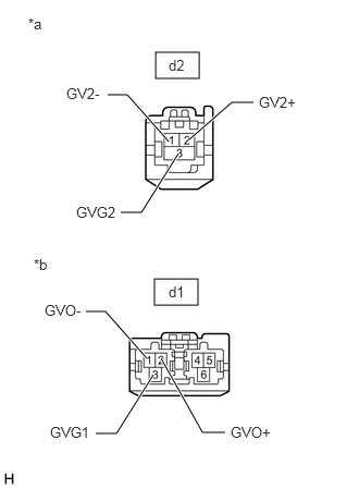
E368007C54
1.49,0.5 1.906,0.75 0.417,0.25 1.479,2.667 1.896,2.917 0.417,0.25 1.156,2.031 1.354,2.031 1.354,2.031 1.708,1.469 true 1.813,1.333 2.219,0.979 2.219,0.979 2.427,0.979 true 1.031,0.906 1.219,0.906 1.219,0.906 1.615,1.354 true 1.542,3.427 1.938,4.135 1.938,4.135 2.156,4.135 true 0.823,2.979 1.01,2.979 1.01,2.979 1.406,3.427 true 0.917,4.146 1.115,4.146 1.115,4.146 1.469,3.583 true 0.271,0.146 0.583,0.302 0.313,0.156 10 false *a 0.323,2.448 0.635,2.604 0.313,0.156 10 false *b 1.615,0.542 2.083,0.792 0.469,0.25 10 false d2 1.615,2.708 2.146,3 0.531,0.292 10 false d1 2.479,0.896 3.052,1.125 0.573,0.229 10 false GV2+ 0.635,0.813 1.208,1.042 0.573,0.229 10 false GV2- 0.729,1.948 1.302,2.177 0.573,0.229 10 false GVG2 0.479,4.052 1.052,4.281 0.573,0.229 10 false GVG1 0.427,2.885 1,3.115 0.573,0.229 10 false GVO- 2.208,4.052 2.781,4.281 0.573,0.229 10 false GVO+
*a Front view of wire harness connector
(to Radio and Display Receiver Assembly)
*b Front view of wire harness connector
(to Navigation ECU)


Disconnect the d1 navigation ECU connector.


b.

Disconnect the d2 radio and display receiver assembly connector.


c.

Measure the resistance according to the value(s) in the table below.

Standard Resistance:
Tester Connection Condition Specified Condition
d1-1 (GVO-) - d2-1 (GV2-) Always Below 1 Ω
d1-2 (GVO+) - d2-2 (GV2+) Always Below 1 Ω
d1-3 (GVG1) - d2-3 (GVG2) Always Below 1 Ω


Result:
Proceed to
OK
NG


OK

3.REPLACE NAVIGATION ECU

NG

REPAIR OR REPLACE HARNESS OR CONNECTOR

3.REPLACE NAVIGATION ECU
a.

Replace the navigation ECU with a new or known good one.

Click hereAudio / Visual / Telematics>NAVIGATION / MULTI INFO DISPLAY>NAVIGATION ECU>REMOVAL


Result:
Proceed to
NEXT


NEXT

4.CHECK DTC
4.CHECK DTC
a.

Clear the DTCs.

Body Electrical > Navigation System > Clear DTCs
50002 212

b.

Press the "MAP" switch and check for DTCs.

Body Electrical > Navigation System > Trouble Codes
50001 212
OK:

No DTCs are output.


Result:
Proceed to
OK
NG


OK

END (NAVIGATION ECU IS DEFECTIVE)

NG

REPLACE RADIO AND DISPLAY RECEIVER ASSEMBLY