A25A-FXS, A25B-FXS ENGINE MECHANICAL REAR CRANKSHAFT OIL SEAL REMOVAL
CAUTION / NOTICE / HINT
The necessary procedures (adjustment, calibration, initialization or registration) that must be performed after parts are removed and installed, or replaced during rear crankshaft oil seal removal/installation are shown below.
| Replaced Part or Performed Procedure | Necessary Procedure | Effect/Inoperative Function when Necessary Procedure not Performed | Link |
|---|---|---|---|
|
*1: Learning can also be performed using the GTS. Click here( *2: Even when not replacing the part, it is necessary to perform the specified necessary procedures after installation. *3: If the vehicle height has changed due to suspension or tire replacement |
|||
| Auxiliary battery terminal is disconnected/reconnected | Perform steering sensor zero point calibration | Lane Control System | ( ) |
| Parking Support Brake System*1 | |||
| Pre-collision System | |||
| Memorize steering angle neutral point | Parking Assist Monitor System | ()
|
|
| Panoramic View Monitor System | ()
|
||
| Initialize back door lock | Power Door Lock Control System | ()
|
|
| Reset back door close position | Power Back Door System | ()
|
|
| Replacement of ECM | Perform Vehicle Identification Number (VIN) registration | DTC is output | ()
|
| Gas leak from exhaust system is repaired | Perform Inspection After Repair | ·
Poor idle, etc. ·
Engine start function, etc. |
()
|
| Replacement of inverter with converter assembly | Resolver learning | ·
DTCs are stored ·
Slight vibration at a vehicle speed of 5 km/h (3 mph) or less ·
Shock or vibration during acceleration |
for 2WD:()
for 4WD/AWD:( )
|
| Replacement of hybrid vehicle transaxle assembly | ·
Resolver learning ·
Initialize resolver |
||
| Replacement of front bumper assembly*2 | ·
Measurement of ultrasonic sensor detection angle ·
Ultrasonic sensor detection angle registration |
Parking Support Brake System | ()
|
| Front television camera view adjustment | Panoramic View Monitor System | ()
|
|
Replacement or removal and installation of 2 or more parts:
·
Front television camera assembly, radiator grille sub-assembly or front bumper assembly ·
Rear television camera assembly ·
Side television camera assembly LH or outer rear view mirror assembly LH ·
Side television camera assembly RH or outer rear view mirror assembly RH |
Television camera view adjustment | Panoramic View Monitor System | ()
|
| Suspension, tires, etc.*3 | ·
Measurement of ultrasonic sensor detection angle ·
Ultrasonic sensor detection angle registration |
Parking Support Brake System | ()
|
| Rear television camera assembly optical axis (Back camera position setting) | Parking Assist Monitor System | ()
|
|
·
Parking assist ECU initialization ·
Adjust steering angle |
Panoramic View Monitor System | ()
|
|
| Front wheel alignment adjustment | Perform "Calibration". | ·
DTCs are stored ·
ABS warning light illuminates ·
Brake warning light / yellow (minor malfunction) illuminates ·
Slip indicator light illuminates ·
VSC disabled or malfunctions |
()
|
- NOTICE:
-
This procedure includes the removal of small-head bolts. Refer to Small-Head Bolts of Basic Repair Hint to identify the small-head bolts.
-
Click hereGeneral>INTRODUCTION>REPAIR INSTRUCTION>PRECAUTION
PROCEDURE

 30900
1.REMOVE HYBRID VEHICLE TRANSAXLE ASSEMBLY
31270
2.REMOVE TRANSMISSION INPUT DAMPER ASSEMBLY
Using height adjustment attachments and plate lift attachments, place the engine assembly on a flat level surface.
- NOTICE:
- ·
Using height adjustment attachments and plate lift attachments, keep the engine assembly horizontal.
·To prevent the No. 2 oil pan sub-assembly from deforming, do not place any attachments under the No. 2 oil pan sub-assembly of the engine assembly.
·Using an engine sling device and engine lift, secure the engine assembly before servicing.
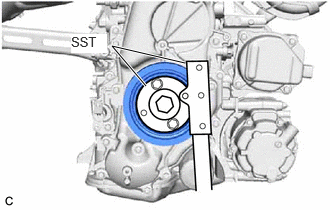
Using SST, hold the crankshaft pulley assembly.
- SST
- 09213-54015
09330-00021
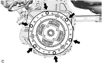
Remove the 6 bolts and transmission input damper assembly from the flywheel sub-assembly.
13405
3.REMOVE FLYWHEEL SUB-ASSEMBLY
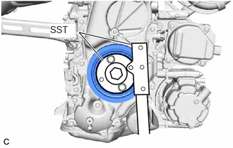
Using SST, hold the crankshaft pulley assembly.
- SST
- 09213-54015
09330-00021
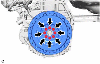
Remove the 8 bolts and flywheel sub-assembly from the crankshaft.
19315
4.REMOVE NO. 1 CRANKSHAFT POSITION SENSOR PLATE
Type A:
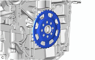
Remove the No. 1 crankshaft position sensor plate.
Type B:
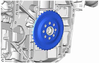
Remove the No. 1 crankshaft position sensor plate.
11401L
5.REMOVE REAR ENGINE OIL SEAL
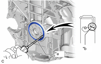
| *a | Protective Tape |
| *b | Cut Position |
Using a knife, cut off the lip of the rear engine oil seal.
Using a screwdriver with its tip wrapped with protective tape, pry out the rear engine oil seal.
- NOTICE:
-
Be careful not to damage the crankshaft.