A25A-FXS, A25B-FXS COOLING FLOW SHUTTING VALVE REMOVAL
CAUTION / NOTICE / HINT
The necessary procedures (adjustment, calibration, initialization or registration) that must be performed after parts are removed and installed, or replaced during flow shutting valve (water by-pass hose assembly) removal/installation are shown below.
| Replaced Part or Performed Procedure | Necessary Procedure | Effect/Inoperative Function when Necessary Procedure not Performed | Link |
|---|---|---|---|
|
*1: Learning can also be performed using the GTS. |
|||
| Auxiliary battery terminal is disconnected/reconnected | Perform steering sensor zero point calibration | Lane control system | ( ) |
| Parking Support Brake System*1 | |||
| Pre-collision System | |||
| Memorize steering angle neutral point | Parking Assist Monitor System | ()
|
|
| Panoramic View Monitor System | ()
|
||
| Initialize back door lock | Power Door Lock Control System | ()
|
|
| Reset back door close position | Power Back Door System | ()
|
|
| Replacement of inverter with converter assembly | Resolver learning | ·
DTCs are stored ·
Slight vibration at a vehicle speed of 5 km/h (3 mph) or less ·
Shock or vibration during acceleration |
for 2WD:
( )
for 4WD/AWD: ( )
|
| Replacement of ECM | Perform Vehicle Identification Number (VIN) registration | DTC is output | ()
|
PROCEDURE

 G9200
1.REMOVE INVERTER WITH CONVERTER ASSEMBLY
2.DRAIN ENGINE COOLANT (for Engine)
16260
3.REMOVE FLOW SHUTTING VALVE (WATER BY-PASS HOSE ASSEMBLY)
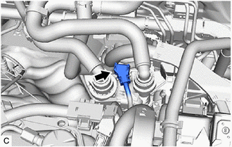
Disconnect the flow shutting valve (water by-pass hose assembly) connector.
Disconnect the outlet heater water hose B connector from the No. 2 water by-pass pipe sub-assembly.
- NOTICE:
-
Remove any foreign matter on the No. 2 water by-pass pipe sub-assembly and outlet heater water hose B connector before performing this work.
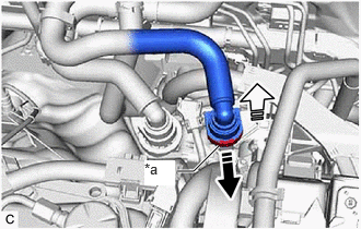
| *a | Retainer |

|
Pull out |

|
Pull off |
Pull out the retainer to disengage the lock claws and pull off the outlet heater water hose B connector.
Check that there is no foreign matter on the sealing surfaces of the disconnected water lines. Clean them if necessary.
Cover the disconnected No. 2 water by-pass pipe sub-assembly and outlet heater water hose B connector with plastic bags to prevent damage and contamination.
Disconnect the inlet heater water hose B connector from the flow shutting valve (water by-pass hose assembly).
- NOTICE:
-
Remove any foreign matter on the flow shutting valve (water by-pass hose assembly) and inlet heater water hose B connector before performing this work.
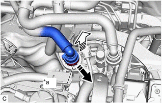
| *a | Retainer |
|
|
Pull out |
|
|
Pull off |
Pull out the retainer to disengage the lock claws and pull off the inlet heater water hose B connector.
Check that there is no foreign matter on the sealing surfaces of the disconnected water lines. Clean them if necessary.
Cover the disconnected inlet heater water hose B connector with a plastic bag to prevent damage and contamination.
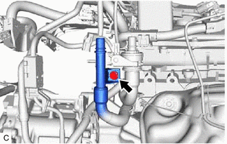
Remove the bolt to disconnect the No. 2 water by-pass pipe sub-assembly.
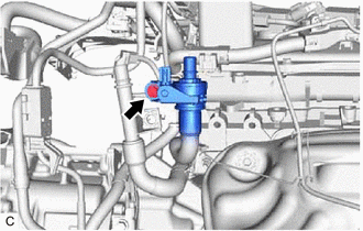
Remove the bolt to disconnect the flow shutting valve (water by-pass hose assembly).
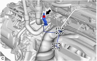
Disengage the 2 wire harness clamps.
Remove the bolt and wire harness clamp bracket.
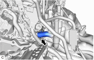
Slide the clip and disconnect the flow shutting valve (water by-pass hose assembly) from the water by-pass outlet sub-assembly.
- HINT:
-
Use a container to catch any engine coolant which flows out of the flow shutting valve (water by-pass hose assembly) and water by-pass outlet sub-assembly.